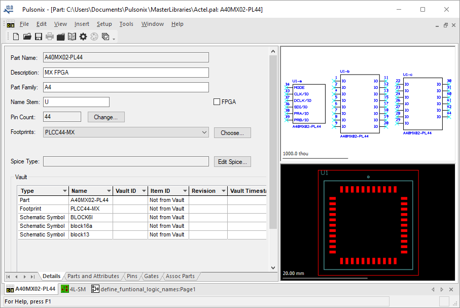
This overview gives a brief outline of the Parts Editor that is displayed when a new part is created, or when an existing part is opened for editing. The organisation of the actual libraries is described separately in the Libraries Overview.
Locating this option
Available from: Library Manager option > Parts > tab
Using the Parts Editor

The Parts Editor is divided into three sub-windows; each displaying a different facet of the Part - the Part ‘details’, a graphical preview of the Schematic Gates (symbols) defined on the Gates page, and a graphical preview of the PCB footprint that is defined on the Details.
The third portion of the editor are the five tabs across the bottom of the window which are used for various facets of the actual Part definition.
Part Definition tabs
Each tab in this part of the window contains information about a different aspect of the part. More detailed information about each of these tabs is available as indicated in the list below:
- Details - description, part family, name stem, footprints, pin count, Spice model
- Parts and Attributes - part names and part attributes
- Pins - PCB footprint pin names, pin remapping, assigned net names, pin types, pin networks, pin attributes
- Gates - Schematic symbols, logic names, swap groups
- Associated Parts - parts associated with the main part which should also appear in a parts list
Note: a Connector Part has no Gates view and an Associated Part has no Gates or Pins view.
Using the Graphical Views
To help with pin allocation, whenever a pin is selected in any one of the windows, the corresponding pin will be highlighted in the other windows. For the textual view, the Pins or Gates tab must be displayed for the highlighted pin to be visible.
Once the relevant footprint or symbol items have been specified in the part, these views will display the appropriate items as currently defined in the appropriate libraries.
Parts do not “contain” footprints and symbols, they only “reference” them. If for example the item in the footprint library is modified before the part is used in Insert Component in a new design, the footprint from the library will be used.
Some of the standard view operations (Zoom, Pan, View All) are available in the graphical views. The colours can also be changed, by selecting Colours from the shortcut menu; the appropriate colours dialog will be displayed depending on whether you select the option from the footprint or the gates view.
As a shortcut to the item in the library, both the graphical views provide a shortcut menu option to edit the item “in the library”. This will open the selected footprint or Schematic symbol in a new window for editing.
Creating a New Part
There are two mechanisms for creating a new part:
- Use the New Part option from the New option on the File menu.
- Use the New button from the Libraries - Parts page.
Further information about creating Parts can be found on the relevant help page.
Related Topics
Libraries Overview | Libraries - Parts | Insert Component | Colours |