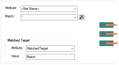
The Track Length Match Rules dialog is used to specify how a ‘group’ of net items matching the match value will be matched against each other. You can also specify additional matched groups, optionally with an extra delay length.
Unlike most other types of rules, all Length Match rules are checked for a match for each net item, not just the first it matches. A net can be in more than one match rule, so order in the list is not important. The general rule matching mechanism is described here.
These rules can apply to the total length of Nets, Sub Nets, Differential Pairs, Differential Pair Chains or Signal Paths.
Shortcuts
Menu: Setup
Default Keys: T
Command: Technology
Locating this option
Available from: Setup menu > Technology option > Rules - High Speed - Track Length Match page
Using the Track Length Match Rule dialog
On selection, the Technology dialog opens, select Track Length Match Rules . The existing Track Length Match Rules for the Technology being used will be presented.

Navigation
The buttons to the right side of the dialog are used to navigate the grid, the general common buttons are detailed on the Technology Navigation page.
Using the editing pane

Attribute Name
A match is when the specified Attribute Name and Match Value match attributes of a net,
signal path or differential pair. So the net item must have the given attribute, and it’s value must
wildcard match the value. The
Wildcard Wizard is enabled using the small icon next to the Match Value
entry: ![]()
Add a Track Length Match Rules using the New button, which will create a row in the table.
Match Length Difference
This value is the maximum length difference (or skew) between any item in the match group.
Matched Target
Under Matched Target, you can define a Net Attribute and Value that can be assigned to a net and used on a Net that should be matched when using the Track Length Match rule. This value can be overridden in the Rules Spreadsheet Options using the Use Match Target Attribute. Without this rule defined, any net can be nominated as the Matched Target in the Rules Spreadsheet.

Once defined in this dialog, the Attribute name should be assign to a Net. It can be added in the Schematic or PCB design.
Extra Delay Length
Use the Extra Match button to add an extra match group to the currently selected group, this adds a new line to the grid. The Attribute Name cell is blank because it is the same as the first line, but you must add a different Match Value.
This is used for two reasons; you can specify a different group of items with a different Match Value without making the Match Value too complicated; the additional group can have an Extra Delay Length skewing their lengths with respect to the other groups.
The Extra Match field is only relevant to extra groups. You can specify that within that extra matched group, an Extra Delay Length is applied. The value can be a positive or negative length. This effectively skews this group by the value defined relative to the first group.


In the example above for Net Name HSE*, the ‘group’ length match is specified but the group also includes extra matches for both CLK and RST. However, as well as RST being included in the group, it also has a value specified for an additional delay length.
This track length will include any adjustments caused by
Track Length Factor,
Layer Change Length or
Export and Import CSV
Use the Export CSV button to export the data in your PCB design into a CSV format file. Using the Export CSV option will provide you with a formatted template ready for you to edit in your own data.
Use the Import CSV button to import data back into the PCB design using a CSV format file.
The data in the file represents a spreadsheet of dialog contents with the data headings along the top row.
Match Sub Net
When the Attribute field is set to Sub Net Name, the Only Match Sub Nets Within the Same Net check box will be displayed. If you select this, the match will only be made on that part of the sub net that matches.

Units
The Units button allows you to locally switch between Metric and Imperial units whilst in this dialog. Once the dialog is closed, the units revert back to the original design units. If switching to different units to the design units, the value typed will be converted when you next enter this page.
Related Topics
Technology Overview | Using Dialog Grids | Nets | Differential Pairs | Signal Paths | Sub Nets | Track Length Factor | Layer Change Length | Design Rule Check | Export CSV | Import CSV