Use this to set up preferences that affect how tracks behave when being added or edited in a PCB design.
Shortcuts
Default Keys: O
Default Menu: Tools
Command: Options
Locating this option
Available from: Tools menu > Options > Edit Track > page
Using the Edit Track Tab
All of these options are saved to the registry, so they apply to all the designs you load into the application. Most of these switches can also be changed using the shortcut menu whilst using Edit Track.
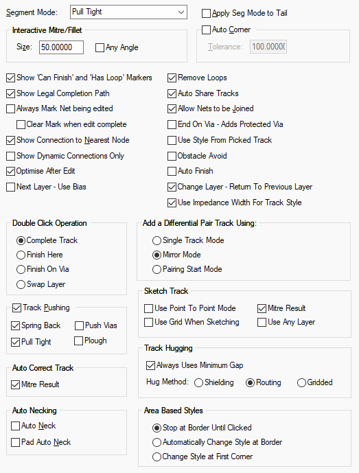
Track Segment Editing
Segment Mode
This defines the default restrictions on the orientation of segments when creating or editing a track. You can change the Segment Mode at any time whilst creating or editing a shape by using the Change Segments option on the Edit Track context menu.
| Free Angled |
 |
| Orthogonal |
 |
| Orthogonal (Mitre) |
 |
| Orthogonal (Fillet) |
 |
| 45 Angled |
 |
| 45 Angled (Fillet) |
 |
| Curved |
 |
| Restricted Movement |
 |
Interactive Mitre/Fillet
Defines the size of mitres and fillets which are added interactively to round off sharp corners between two straight track segments. They are added when using Edit Mitre or the Segment Modes Orthogonal (Mitre), Orthogonal (Fillet) and 45 Angled (Fillet).
A mitre is a straight line across the corner, and a fillet is a curve to produce rounded corners. On a 90 degree corner between two orthogonal lines they will look like:
Mitre  | Fillet  |
| Mitre gives fixed size 45 degree angled segments. | Fillet gives fixed size 90 degree curved segments. |
Mitres and Fillets are a fixed size, which is specified in the Size edit box. The Size is the radius of a circle that is a tangent to the lines that meet at the corner. A Fillet will be the part of the circle between the two lines, and a Mitre will be a straight line between the same two points. For 90 degree corners between orthogonal lines, the size will be the orthogonal width and height of the mitre.
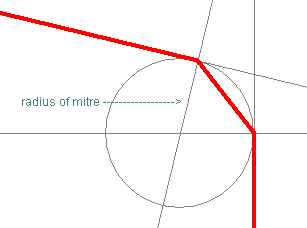
Check the Any Angle box to allow Edit Mitre to mitre or fillet between straight lines with any angle between them. Leave unchecked to only allow mitres or fillets between lines orthogonal and perpendicular to each other.
Auto Corner
This is an advanced editing feature which allows tracks to be drawn without having to click the mouse at each corner. (Note, this feature does not operate in Free segment mode and is not needed in Pull Tight mode which automatically corners anyway). You must define a tolerance, which is the distance the cursor must move away in a perpendicular direction from the first segment you are adding before a corner is added. You can still click at any time to add a corner. It is recommended that the Tolerance is larger than any grid and mitre size you are using.

In the example the cursor is at the bottom of the second selected (white) segment. As you move right the first selected segment gets longer. When you move down so that the second selected segment is longer than the auto corner tolerance, a corner is added and the first selected segment is complete.
Apply Seg Mode To Tail
When checked, applies the same segment mode to the lead and trailing segments when editing an existing track segment. This option does not apply to Pull Tight mode.
No Seg Mode To Tail  | Apply Seg Mode To Tail  |
| Trailing segment is at a free angle. | Segment mode is applied to the trailing segment. |
Other Edit Track Switches
Show ‘Can Finish’ and ‘Has Loop’ Markers
These take the form of Modal Cursors or, if Modal Cursors not enabled (see General Options), then dynamic markers are drawn in the highlight colour. They appear at the cursor position to indicate that clicking would do something different from just the normal add corner. The following 3 Markers exist:
Can Finish Here  | Can Finish On Via  | Loop To Remove  |
| Left click whilst this marker is shown will result in the track being finished and attached to the item underneath the cursor. | Control Click whilst this marker is shown will result in the track being finished on a via through to the item underneath the cursor. | Left click whilst this marker is shown will result in a loop in the track being removed from the track. |
Show Legal Completion Path
Only available if editing a PCB connection, or adding a new track and using Show Connection To Net. This switches on or off the display of a legal completion path from the dynamic track end to the target item at the end of the unrouted connection. It is also available when editing Differential Pairs in Mirror Mode or Pairing Mode.
The completion path will only be displayed if the track can be completed to the target item using the current segment mode in two or less segments without introducing any spacing errors. It will be displayed using hollow segments in the “Unfinished” highlight colour.
Use it to know if there is a simple legal path for use by Complete As Track from the current track position. If it is displayed the Complete function will use it and not attempt completion with a more complicated path using a routing algorithm.
The completion path can be used alongside pad auto necking, which will show a necked segment at the end of the completion path, allowing for insertion of necked segments into pads.
Always Mark Net being edited
Use this to show the net currently being edited in the Marked Net highlight colour**. Clear Mark when edit complete** will cause the edited net to become unhighlighted again. Otherwise, it will remain highlighted until the next net is edited.
Show Connection To Nearest Node
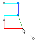 | Use this when adding tracks to show a line (connection) between the moving cursor and the nearest item that you can finish on on the same net. Note, when you are editing a connection you get two lines from the cursor, one to the nearest node and one to the original connection end (see picture). |
Show Dynamic Connections Only
This option has an effect when moving items attached to nets and when editing tracks, differential pairs or bus routes. Use it to hide all unrouted connections that are not dynamic during the interactive operation. It will only show the dynamic connections if they were already visible. This option is useful in the early stages of layout when there are a lot of connections on the screen, enabling you to just view the connections attached to the component or tracks you are moving or editing.
Optimise After Edit
Use this when editing tracks to cause Optimise to be run on the net after editing is completed. This will ensure unrouted connections are only shown on the net where the minimal breaks occur.
Next Layer - Use Bias
When editing a track, with this option selected, the Next Layer and Previous Layer commands will skip layers defined in your Technology Layers with a bias of Power Plane, No Tracks or Minimum Tracks.
With this option left unchecked, the Next/Previous Layer commands will swap to any electrical layer with any bias.
Remove Loops
Use this to allow loop removal when tracks are finished. This is the normal mode, but occasionally you may want to create loops in tracks. If this mode is not checked, the loop removal marker is not used. Loops will only be removed within the track path, not anywhere on the net.
Auto Share Tracks
Use this to automatically remove overlaid tracks after finishing editing or moving a track. A junction will be created where the overlaid tracks end. If this option is not checked, any overlaid tracks will remain so. You can always use the Share Tracks option to remove all overlaid tracks in the design at a later stage.
Allow Nets To Be Joined
Switch this off to avoid picking items that are on a different net to the net that is being edited. When you are not merging nets this makes the finish marker more useful as it only appears when you are over items on the same net.
End On Via - Adds Protected Via
Use this when adding tracks to protect vias added using the End On Via option against automatic deletion and layer span changes. If left unchecked the via will take what ever protection is set up in the Defaults or Net Styles settings.
Use Style From Picked Track
Enable this option to force the adding of new tracks to take their style from any track segment that was picked to start the new track on.
Obstacle Avoid
Use this when adding tracks to avoid obstacles by automatically adding a corner to change direction when you come up against an obstacle.
In this mode you can automatically remove any corners that have been added by re-tracing the cursor back over the track (like in auto corner).
Note: This mode can only be used if Online DRC is on and set up to use Continuous checking, and the segment mode is not Pull Tight (which will wrap around obstacles anyway).
Auto Finish
Use this option when adding a new track to automatically finish it when it’s free end is moved over an item that it is allowed to connect to.
Change Layer - Return To Previous Layer
Use this option when adding a new track to switch between the current and previous layer, when using Swap Layer or Change Layer. When not checked, the alternate layer defined in Track Defaults is used.
Use Impedance Width For Track Style
Use this switch to enable automatic track width calculations based on your required impedance. You must also have a suitable Layer stack defined as well as the Layer Material and Thickness. The actual track impedance required is defined in the Track Impedance Rules dialog.
Once track routing is started, all these facets are combined to generate a track width.
Double Click Operation
Complete Track - Double Click attempts to finish the track to the end of the attached connection. It will use the current segment mode to complete the track. If Online DRC is enabled in Continuous mode and there is an obstacle in the way of the attempted finish path, a more intelligent routing algorithm will be used to try to complete the track.
Finish Here to let Double Click simply finish the track in space.
Finish On Via to let Double Click finish the track and add a via at the end of the track.
Swap Layer to let Double Click insert a via and continue the track on the opposite layer.
Track Pushing
When adding, editing or moving a track segment, existing tracks may get in the way. With Track Pushing enabled, nearby existing tracks are Pushed away from the track being edited, making design rework much easier. The pushed tracks are frozen at their current location when a corner is added and the pushing begins again. Only a limited amount of effort is applied to the pushing, as it is not desirable for a small track modification to push tracks across a large area of the design. With Online DRC enabled, the pushing will not introduce design rule errors, otherwise tracks may be pushed over other items, causing errors.
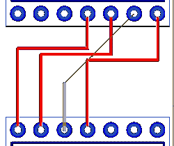 | 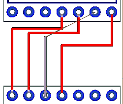 | 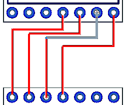 |
When Spring Back is enabled, pushed tracks will move back to their original position as the edited track is move away. Spring Back is recommended. It is also possible to push vias using the Push Vias option. This option will allow vias to be moved, you should be aware that moving a via may make it necessary to rework tracks on other layers.
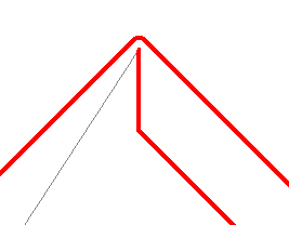
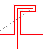
There are a couple of options to control how the pushed tracks are smoothed. The pictures above show the default orthogonal mode. Below shows the Pull Tight mode where the pushed track is smoothed to reduce the number of corners leaving orthogonal and 45 degree segments. Plough mode will cause minimal changes to the existing track and the track will be shaped around the pushing track.
| Pull Tight Mode | Plough Mode |
 |  |
Differential Pair Automatic Start Mode
When you start routing a track at the start of a differential pair a special edit mode will be entered to help gather the tracks together to start adding paired track segments. In the Add a Differential Pair Track Using section you can choose the mode that you want to use.
Single Track Mode - Just adds the single track you are editing and does not route the track on the other net.
Mirror Mode - Adds a mirrored copy of the track you are editing, on the other net of the pair. Movement of the tracks will automatically be restricted so that they do not become closer together than the differential pair gap. Left click when they are close to start pairing.
Pairing Start Mode - Gathers the two tracks by routing to two junctions representing the start of the paired section. Moving the cursor moves the junction pair to the required position, and left click starts the pairing.
Track Hugging
When adding or editing PCB tracks you can use a mode called Track Hugging to follow the path of an existing track or design shape. Check the Always Uses Minimum Gap option to force track hugging to always hug to the minimum gap allowed by the spacing rules. Leave unchecked to allow track hugging to hug at the initial distance from the track to the shape, or to type a required gap.
Hug Method - Choose one of the following methods to change how the track will hug the obstacles.
- Shielding - Adds tracks that hug the obstacles as tight as possible, introducing arcs around pads and sharp corners.
- Routing is like shielding, but will add 45 degree lines around pads and sharp corners.
- Gridded will add a track with all segments a multiple of 45 degrees and snapped to the next track grid position away from the obstacle.
Sketch Track
Sketch Track allows you to create tracks by roughly drawing a path for the system to follow.
Use Point To Point Mode option means that you simply define points to route to, rather than sketching a continuous path.
The Mitre Result option causes the resulting track path to be mitred using the Auto Mitre tool.
Use Any Layer allows you to sketch a track path which can be routed on any track layer, the current layer is used if possible, but vias can be added as required. Otherwise, the tracks will stay on the layers they were sketched on.
Use Grid When Sketching controls if the sketch is to be completely free hand or gridded.
Area Based Styles
This option determines what happens at the border of an area marked for Area Based Styles when a track style change is defined in the design technology Net Styles entries.
You can choose one of three actions:
- Stop At Border Until Clicked: A corner is placed on the border and the style changed at that point.
- Automatically Change Style At Border: A corner is automatically placed on the border and the style changed.
- Change Style At First Corner: You can continue into the area and a style change is only made when you place a corner.
Continuous Online DRC needs to enabled for the first two options to work.
Auto Correct Track
The Auto Correct Track option allows you to ‘correct’ tracks by moving their segments and swapping sides to avoid errors. The Mitre Result switch causes the corrected track path to be mitred using the Auto Mitre tool.
Auto Necking
The Auto Neck option allows you to neck to and from pads or through gaps that would normally cause a DRC error when using Online DRC. It can be used when routing anywhere in the design and will neck down the current segment to avoid DRC errors. Once avoided, it then reverts to the regular style after passing the items that would cause the error, you can then continue routing.
With this option enabled, the currently selected track will neck down to a smaller track style; the alternate track style defined in Net Styles dialog to avoid DRC errors.
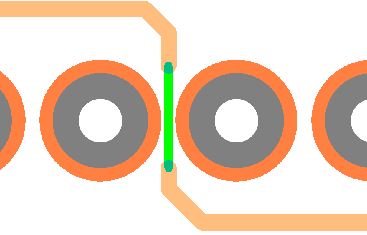
This mode can be used by either clicking directly on the pad or using the completion shape. When using the completion shape for pad auto necking, it will show the necked segment at the end of the completion shape.
The Pad Auto Neck option allows a track to neck into, and from pads. The width of the necked track will be a percentage of the size of the pad. This check box enables the feature. The rules for it’s use are defined in the Pad Track Neck Rules dialog. This dialog enables you to set the Pad Track ratio as a Percentage and the length of the necked track will be the minimum length value defined.
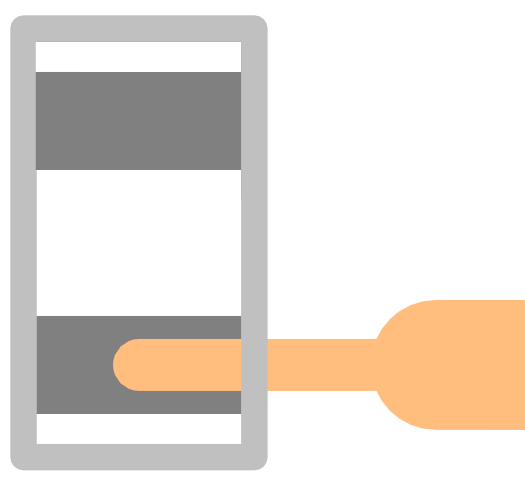
On the Pad Track Neck Rules dialog, under Global Pad Track Neck Rules, with the Always Create Style With Correct Width check box selected, if the calculated width of the necked track does not match a style currently in the design, a new track style will be created at the percentage width to that of the pad it is exiting. If the required style matches the style defined for the net in the Technology Net Styles dialog then this will be used.
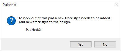
If this option in unchecked, when the track style is created a confirmation dialog will appear to confirm if you want to add the track style to the design. Pad necking requires this new track style, so if the style is not added to the design necking will not occur.
If this option is checked, when the track style is created no confirmation dialog will appear. The track style will be added to the design without warning.
Other Options Tabs
| General Options: | Design Backups | Display | Edit Shape | File Extensions | Find | Folders | General | In-Place Names | Macros | Move | Multi-Screen | Pan & Zoom | Resolve Net Names | Select | Synchronisation | Tooltips | Warnings |
| PCB Options: | Interaction | Online DRC | Track Length Limits |
| SCM Options: | Edit Connection | Interaction | Online ERC |
| Footprint Options: | Edit Breakout |
Related Topics
Breakouts | Edit Track | General Options | Edit Mitre | Online DRC | Share Tracks | Sketch Track | Technology - Track Length Rules | Technology - Pin Networks
