Net Styles provide a means of defining the default Track Styles, Via Style and Via Protection to be used when routing PCB designs.
This enables you to achieve the following:
- Use wildcard characters to match Net items to reduce the number of duplicate default style definitions.
- Define different default track styles for layers and areas.
- Define different default via styles to be used for each layer span.
- Define default via protection (against automatic deletion and span reduction) to be used.
- Define different default track and via styles to be used within specific areas. See Defining Styles By Area for more details.
Shortcuts
Menu: Setup
Default Keys: T
Command: Technology
Locating this option
Available from: Setup menu > Technology option > Rules - DFM/DFT - Net Styles page
Using the Net Styles dialog
On selection, the Technology dialog opens, select Net Styles. The existing Net Styles for the Technology being used will be presented.

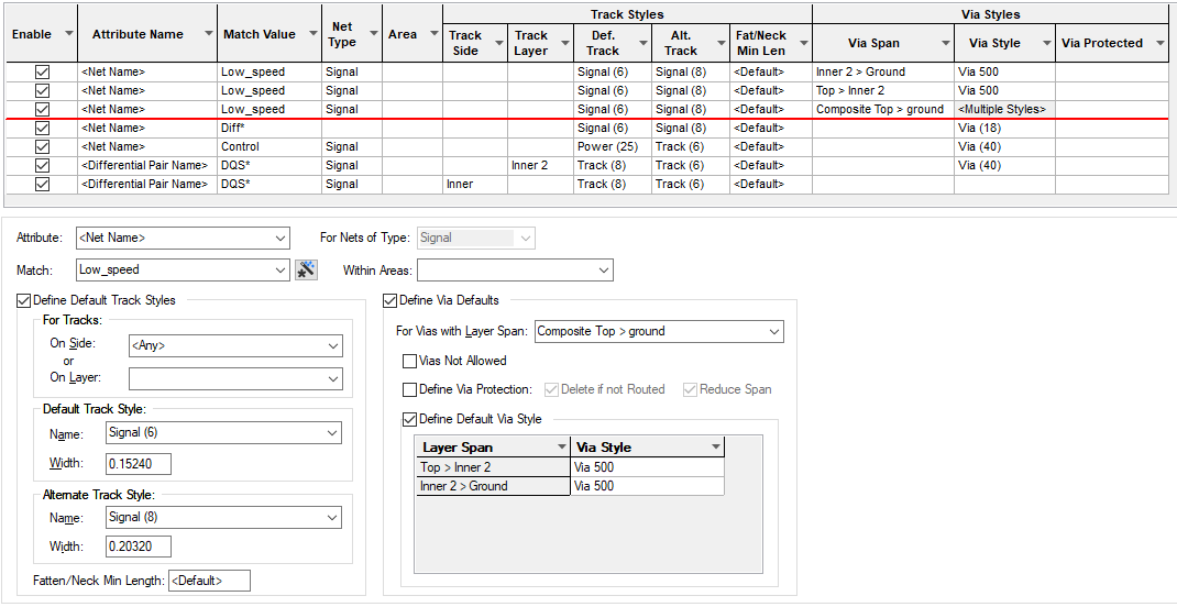
When adding a new track or via to the design, the style to be used is searched for through the Net Styles entries defined in the design, in the order defined in this dialog. The search will continue until a match is found taking into consideration the net, track layer, via layer span and an area name (if within a styles override area).
You must ensure the more specific entries are nearer the top of the table and the general definitions using wildcard names and blank fields are at the bottom of the table.
A rule specify the default track styles or the default via styles, or both of these by checking the Define Default Track Styles or the Define Via Defaults boxes.
If none of these Net Styles entries match, then the styles defined in Defaults - Net Styles will be used.
Navigation
The buttons to the right side of the dialog are used to navigate the grid, the general common buttons are detailed on the Technology Navigation page.
A special note about Where Used All in this dialog. This button will report every net that is allocated
to a rule. If you wish to find any nets that do not come under any rule, add a new rule for
Using the editing pane
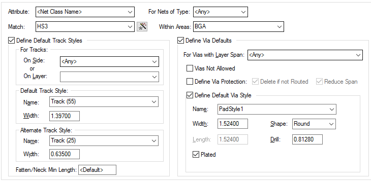
This pane allows you to define how the rules will be applied.

For Nets Of Type
This is an additional match condition which allows you to specify the net type (so you can define separate rules for Signal, Ground & Power. Leave as Any (blank) when not required. (This was mainly provided for backward compatibility).
Within Areas
Enter a name here if the styles are only to be used within design areas whose names match the entered string. Only areas that are marked for styles override will be considered.
See Defining Styles By Area for more details.
Note: if the style used entering the area is not the one defined on the net within the Net Styles dialog before it enters the area, the Area rule will not be used.
Define Default Track Styles
Check the Define Default Track Styles box to specify the Track Styles.
For Tracks
You can define the track styles for specific layers or side. If you choose to specify a layer name, this can be a wildcard string which may match several actual layer names.
Select a Track Side if the track styles in this entry are only to be used for tracks that are on a specific side of the board, or on an inner or outer layer. This allows you to specify different default track styles to be used on the top or bottom of the board for particular net classes. Use Any if the side does not matter.
Default/Alternate Track Style
You specify two Track Styles, the Default which is the one normally used, and the Alternate which is an alternative style. Between them, they define the minimum and maximum widths to be used during routing. When manual routing, you can easily switch between these two styles.
Fatten/Neck Min Length
The Neck Track tool also uses the two default styles. You can specify a minimum length which must be achieved before the tool will change between normal and necked widths. This prevents very small sections of necked track.
Define Via Details
Check the Define Via Defaults box to specify the Via Style and Via Protection defaults.
For Vias with Layer Span
Select a Via Layer Span if the via details in this entry are only to be used for vias that
use a specific layer span. This allows you to specify different default via sizes and protection to be
used for each layer span in the design. Use
Vias Not Allowed
Check the Vias Not Allowed box if you would prefer vias not to use a particular layer span.
The next best layer span available will be used. For example you might want to always use through-hole
vias within a certain area, and so you could set up an entry for that area with layer span
Define Via Protection
Check the Define Via Protection box if you want to change the default via protection against automatic changes for this Net Styles entry. Uncheck the Delete if not Routed box to stop vias from being automatically removed when all tracks attached to them are deleted or moved to the same layer. Uncheck the Reduce Span box to stop vias from having their spans automatically reduced to a better fit span when changing the layers of attached tracks.
Define Default Via Style
Check the Define Default Via Style box to specify a default via style to be used for this entry. When entering styles, you can select an existing style by selecting the appropriate Style name from the drop down list, or you can enter the parameters, which will select an existing matching style, or allow you to create the Style when you click on the OK button.
Composite Spans & Stacked Vias
If you select a Composite Span, then you must select the pad style to be used for each of the spans which make up the composite. Only nets which have a matching Net Styles entry can use Stacked Vias. When editing a track, Change Layer may then create a stack of vias to change layer, rather than a single via. This may be very useful when using a Micro-via technology.

Export and Import CSV
Use the Export CSV button to export the data in your PCB design into a CSV format file. Using the Export CSV option will provide you with a formatted template ready for you to edit in your own data.
Use the Import CSV button to import data back into the PCB design using a CSV format file.
The data in the file represents a spreadsheet of dialog contents with the data headings along the top row.
Units
The Units button allows you to locally switch between Metric and Imperial units whilst in this dialog. Once the dialog is closed, the units revert back to the original design units. If switching to different units to the design units, the value typed will be converted when you next enter this page.
Related Topics
Technology Overview | Using Dialog Grids | Defining Styles By Area | Net Classes | Using Dialog Grids | Track Styles | Pad Styles | Export CSV | Import CSV