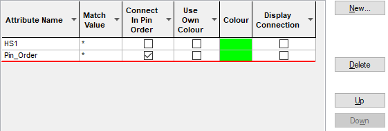
A Sub Net is a group of pins which are part of a larger net. By defining a Sub Net, you can apply rules to the pads and the connections between them. A Sub Net is defined by a pad attribute which is common to those pins. The Create Sub Net dialog enables you to nominate the pins as well as define and add the attribute to them in one step.
The name of the sub net is the name of the defining pad attribute, if the match value is anything other than *, then that name of the sub net is of the form attribute name=match value.
Note that a single entry in this table will only define one sub net in a given net, but can define several sub nets in different nets. There may be several nets which contain pins with the given attribute, each of these nets will contain a different sub net.
A sub net is fundamentally defined by the pin attribute, copying components may create sub nets in new nets.
The Net Items page provides an overview of all the net styled items in Pulsonix. This enables you to see the differences and to assess their use for your required usage.
Shortcuts
Menu: Setup
Default Keys: T
Command: Technology
Locating this option
Available from: Setup menu > Technology option > Nets - Sub Nets page
Using the dialog
On selection, the Technology dialog opens, select Sub Nets. The existing Sub Nets for the Technology being used will be presented.

Navigation
The buttons to the right side of the dialog are used to navigate the grid, the general common buttons are detailed on the Technology Navigation page.
By right clicking in the grid, you can select Advanced View from the context menu. This opens the grid to expose attribute rules and matches:

Using the editing pane

Use the New button to create a new Sub Net, this will launch the Create Sub Net dialog from which to create a new Sub Net. From this dialog, the components, pins and net names are chosen from which to create the Sub Net.
Click here to get more information about Creating Sub Nets.
The Attribute Name, Match Value and Value Type are as defined in the Create Sub Net Dialog.
If the sub net matches a Track Length Rule or Track Length Match Rule it will be shown in the table. You can also use this dialog to define a new rule by completing the values here.
The Attributes tab shows the attributes defined on the currently selected Sub Net. These are attributes on the sub net itself, and should not be confused with the pin attribute which defines the sub net. The main reason for adding attributes to a sub net, is to make it match length rules.
The Rules tab gives a summary of the rules which match the currently selected Sub Net.
Own Colour
Use Own Colour enables you to highlight the sub net using it’s own colour.
Force Display Connections
When Connections are switched off in the design, selecting the Force Display Connections check box will force the connections in this sub net to be visible. This overrides the Connection and Net colour setting in the Colours dialog.
Connect In Pin Order
The Connect In Pin Order check box (attribute value order) forces the connection pattern in the design to be defined by the attribute values on the pins. This order is used to override the Optimise Nets option in the design. (This type of pattern is also known as daisy chain routing).
If left unchecked (the default selection), the pin order as defined in the Sub Net Pads In The Net will be used.
The connection order is defined by an alphanumeric comparison of the sub net pin attribute values. The connections between the pins should form a chain or tree, such that each pin forms a link between pins with lower values and those with higher values.
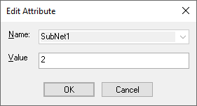
You can also add a Pin_Order attribute and a Value to a Pin on the net in the design using the Insert Attribute option from the context menu after selecting the Pin. The use of this attribute can be selected when in the Create Sub Nets dialog and selecting the Use Pin attributes radio button at the top of the dialog. during the create sub Nets process, if a user pin attribute is not selected, a default SubNet pin attribute will be assigned for you. The Value for this can be edited using the Edit Value button.
Once this dialog is exited, you will have to run the Optimise Nets option to force the connection pattern.
Nets Containing Sub Net
When a sub net is selected from the grid above, Nets Containing Sub Net box displays the list of Nets which contain this sub net.
Sub Net Pads In The Net
The Nets Containing Sub Net box shows all the pins and Branch Points and their side, for the selected sub net. You can add extra pins (or Branch Points) to the net by using the Add box. The Choose Pads For Sub Nets dialog is displayed from which to choose valid items. Once selected these will be added to the Sub Net Pads In The Net list. Now that additional items have been added, you can select them and the Remove button will be available. Pins are added and deleted from the net by adding or deleting the underlying pin attribute on the pin. If the attribute is inherited from the part, it is not possible to delete it.
The Edit Value button is used to change the attribute value on the selected pin. This will dictate the connection order and can be used with the Connect In Pin Order option above.

Rules and Attributes
Sub Nets can have attributes, this is primarily so that you can make them match rules. These attributes should not be confused with the pin attribute which defined the sub net. Suitable rules can also use the in-built attribute, which enables you to create explicit rules for an individual sub net. Attributes are defined using the Attributes tab and the Add, Edit, Delete buttons.
The Rules tab gives you a summary of the rules which currently match the selected sub net. More information about editing these fields can be found on the Rules and Attributes help page.
Export and Import CSV
Use the Export CSV button to export the data in your PCB design into a CSV format file. Using the Export CSV option will provide you with a formatted template ready for you to edit in your own data.
Use the Import CSV button to import layers into the PCB design using a CSV format file.
The data in the file represents a spreadsheet of dialog contents with the data headings along the top row.
Units
The Units button allows you to locally switch between Metric and Imperial units whilst in this dialog. Once the dialog is closed, the units revert back to the original design units. If switching to different units to the design units, the value typed will be converted when you next enter this page.
Related Topics
Technology Overview | Technology - Create Sub Net Dialog | Track Length Rule | Track Length Match Rule | Technology - Attribute Names | Export CSV | Import CSV