This dialog is displayed when the Properties option is chosen with a Component selected. The Component tab is also available from the Properties dialog whenever the item selected is associated with a component such as a Pad or an Attribute.
It shows and allows you to modify properties for the selected Component.
Shortcuts
Default Keys: I or Alt+Enter
Default Menu: Edit
Command: Properties
Locating this option
Available from: Edit menu > Properties option
Available from: Context menu > Properties option
Available from: Shortcut key > I
Using the Component Properties Dialog
As well as the Component properties, additional tabs may be available, depending on the item selected, such as Component Attributes, Nets on Pins and Ungated Pins.
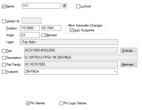
There are subtle differences between the Component Properties dialog show in the Schematic Editor and the PCB Editor. The image below is for the PCB Editor:

Name
Displays the component name. The box is checked if the name is visible. Note that it will only be visible on screen if the ‘Component Name’ attribute is also set to displayed in the Colours Dialog.
 First Free Component Name - Use this button to set
the component name to the first free name that does not yet exist in the design.
Locked
Checked if the component is locked against changes, in which case all other dialog items will be set to read only.
Variant Id
With Variants activated in the Variants dialog you can assign a Variant Id if you wish to use the Advanced Variant feature.
Position
Displays current position of the component, in design units, relative to the design origin. The component is positioned using the origin defined for the footprint or symbol being used to represent it.
Allow Automatic Changes - Auto Footprints
In PCB, by unchecking the Auto Footprints option you can exclude a component from the Auto Footprints option. The default value is for the check box to be selected, allowing automatic changes. You would uncheck this to make specific selections for components that should not be included for the Auto Footprints rules option.
Angle
Displays the Component’s angle of orientation in current angle units. 0.0 degrees = horizontal and 90.0 degrees = vertical.
Mirror
This is checked if the component is mirrored. You can toggle this to mirror or not mirror the component.
Scale
In Schematics, you can scale a symbol. A scale of 1.0 represents the symbol at the size it was designed at. All points are scaled relative to the symbol origin. Styles are not scaled, so all text remains at the same height and lines remain the same width.
Layer
In PCB, this shows which side the component is currently on. For Embedded Components, use this control to set the layer (in this case Mirror will be disabled).
Part
Displays the Part Name for the component. The box is checked if the Part Name is visible. Note that it will only be visible on screen if the ‘Part Name’ attribute is also set to displayed in the Colours Dialog.
Change
Click this to change the part for the selected component(s). A Change Part dialog will be displayed to use to choose the part to change to.
Description
Displays the description of the selected part.
Part Family
Displays the family name of the selected part., or left blank if the part is not a member of a family.
Alternate
Click this to use an alternate part for the selected component(s). An Alternate Part dialog will be displayed to use to choose which part from the family to change to.
Footprint
Displays the Footprint Name for the component. Select an alternative Footprint from the dropdown list. The name box is checked if the footprint name is visible. Note that it will only be visible on screen if the ‘Footprint Name’ attribute is also set to displayed in the Colours Dialog.
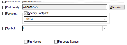
If editing a schematic design, a Specify Footprint check box will be shown. Normally, the schematic designer does not want to control the footprint. Check this if you want to specify exactly which footprint is to be used in the corresponding PCB design.

Synchronise Designs will then ensure that the PCB design is using the required footprint.
You can use Find to find all components that have their footprints
directly defined; they will use the
Symbol
Only present if editing a schematic design. Displays the symbol name for the selected symbol(s). If more than one symbol alternate has been defined for this gate in the part editor, then you can select one of the other symbols from the drop down list.
The box is checked if the symbol name is visible. Note that it will only be visible on screen if the ‘Symbol Name’ is also set to displayed in the Colours Dialog.
Pin Names
Checked if the pin names are visible. Note that they will only be visible on screen if the ‘Pin Name’ attribute is also set to displayed in the Colours Dialog.
Pin Logic Names
Only present if editing a schematic design. Checked if the pin logic names are visible. Note that they will only be visible on screen if the ‘Logic Name’ attribute is also set to displayed in the Colours Dialog.
Message Area
A message may be displayed at the bottom of the screen giving more detail about the part. For example, “Part is defined for PCB only” indicates that the part is defined for use in PCB only and can not be used in Schematics.
Related Topics
Alternate Part | Component Attribute Properties | Component Ungated Pins Properties | Colours Dialog | Change Part | Part Editor - Change Gate Symbol | Embedded Components | Nets on Pins