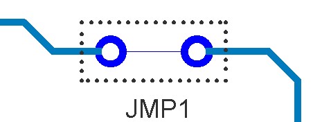
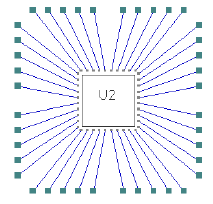
Insert Wire Link is used to add a physical wire to the board to link two items.
Wires and Jumpers provide the ability to make an invisible connective path between two isolated items but for both items to have the same net name. Typically, jumpers are used on single sided boards to jump over tracks where a track on another layer might have been used on a two layer board. The use of wire jumpers enables low cost designs to be produced.
Wires can also be used between Die and Bond pads. A connective path is required between the pads but the process for physically connecting them using a fine wire is either a manual or automatic process.
Note: A wire in Pulsonix is different to a connection or Net which are used to define electrical connectivity, whereas a wire is used for other purposes (as above).
Shortcuts
Default Keys: None
Default Menu: Insert
Command: Insert Wire Link
Locating this option
Available from: Insert menu > Wire Link option
Wire Link Usage
Within Pulsonix wire links can be used for:
- Wire links that can be inserted in any PCB design using the interactive feature (Insert Wire). They can be connected between any legal connective junction, such as pads or vias.
- Jumper Components - wires are contained within a Footprint and used in a Part. These would be either a physical Jumper Part that would be ‘bought’, or used to indicate a specific size of wire jumper link to be inserted. This fixed size would be dependent on the Footprint pad ‘pitch’ and can be varied using alternative Footprints for that Part.
- Die-Bond Wires - As a Bond Wire this allows Die pads and Bond pads to be connected together using a wire to connect them on the same net. This is used within the chip on board option.
Adding the Wire Links
The Insert Wire Link option is used in PCB design to create an interactive link between two items. It works in much the same way as Insert Connection.
A wire can be connected across any pad of any type in the design (including vias, mounting holes etc.). Multiple wires can be added to any pad as well (the wire may not necessarily be assembled though the drill hole).
Wires are added to a Wire layer which can be on the top or bottom side, and notionally sits above the electrical layer. You may want to have a wire layer only on one side, preventing wires from being added to the other side. If you try to add a wire to a design which had no wire layer, you will have the option to automatically add a wire layer. You can add and save the Wire layer to any Technology file if required using the Save Technology option.
Changing the Wire Link Options
While inserting a Wire link You can right click to display the context menu of options available to: Change Net, Change Layer, Change Style and to Mark the Net.
Once the wire link has been inserted, you can select it and use additional options from the context menu to Mitre the wire and the Edit it to create a shape other than the straight line that gets inserted initially. You can also change the Angle of the wire.
Adding Wire Links
When in the Insert Wire Link mode, add the wire as follows:
- Select the start point for the wire by clicking the mouse on an electrically connectable land, such as a pad, via or mounting hole.
- Select the end point for the wire by clicking the mouse, again on an electrically connectable land.
- You may now click to start another wire link, or if you have finished adding wires, exit the mode by pressing Esc on the keyboard, by right clicking the mouse and selecting Cancel Insert Wire Link.
When adding Wires, all the usual checks for creating and joining nets will apply, as if you were adding a connection or track.
Wire Line Styles
The Line Style used for the Wire is taken from the Technology Line Style dialog. The style can be given a thickness and a solid or dotted/dashed style as required.
Displaying Wires
The display of a Wire Link can be set using its own colour under Elec Shapes in the Colours dialog. The dialog differentiates between wires used in a design (added interactively) and Wire Links that are contained in a Footprint (Comp. Wire Links). Wire items only appear in this dialog if defined in the design.
Insulated Wires
All Wire types defined can be marked as Insulated.
You can change the insulated state when added or later through the Wire Properties dialog.
The initial default insulated state can be set in Wire Defaults on the Setup menu.
Plotting Wires
Wires are not normally plotted, they can be but normally they would not.
Wires Report
You can create a report of all the wires in a design using the Report Maker. Within the Report Maker, there is a format file supplied (Wire) which allows you to write out a Wire List. This can also be run from the Reports dialog and reports the Net Name and the X, Y coordinates of the wire span.
Wires and DRC
You can run a Design Rules Check to check for wires that are not insulated or are crossed or are under a Component.
If a wire is specified as Insulated and it crosses another wire then it will not flag an error. An uninsulated wire that crosses with another wire will flag an error. Where one insulated wire crosses an uninsulated wire then no error is flagged.
You can also check whether wires are placed underneath Components.
Wires in Footprints
Wires can be added to a footprint which enables you to create internal connectivity and is used for a Jumper, for example. For internal connections of device or pin sharing, this is more efficiently achieved using a Part pin mapping definition in the Part (see below).
Wires in Parts
Implied ‘internal Wires can be added to a Part definition to indicate internally connected pins. To link pins that are internally connected within a footprint use the pin mapping feature in the Parts Editor - Gates page.
Jumper Parts
A ‘jumper’ would be different to an inserted ‘wire’ in that it would be either a physical Jumper Part that would be ‘bought’, or used to indicate a specific size of wire jumper link to be inserted into the board during manufacture. A jumper still has Wires but they contained within a Footprint for automatic insertion as a Part.

Joining two pads in a footprint with using Insert Wire will create an internal net and force the two pads to be on the same net. The footprint can be used by a Part in the normal way as a regular Part item. Nothing else is required in the library to be able to use the Jumper Part.
The jumper pitch would be a fixed size and would be dependent on the Footprint pad ‘pitch’ used. This can be varied during insertion into the design using alternative footprints for that Part. Use the Next Footprint option to select the next footprint in the Part. You may wish to create a number of jumper footprints that have pad pitches matching manufacturable pitches, for example, 150, 200, 250, 300 thou, or 7.5, 10, 12.5 and 15mm.
For designs where the Jumper only appears on the PCB design and not in the Schematic, a PCB Only Component should be created. These are ignored during Synchronise Design and are not ripped out. Likewise, if you wish to show Jumper Parts in the Schematic design, you must create both the Schematic Symbol and PCB Footprint for the Part definition.
As with wires added interactively into a design, wire positions added into a Footprint can be output using the Wires report.
Wire Bonded Part
Within the Footprint Editor, when inserting a Bond Pad and Die Pad, they can be joined together as a ‘pair’ using a wire. By doing this, you can create a wire bonded footprint.
A connective path is required between the pads but the process for physically connecting them using a fine wire is either a manual or automatic one.
You can define limits on the length of Bond Wire using the Spacing Design Rules within the Technology.
To run this functionality, you must have the Chip On Board license.

The footprint can be used by a Part in the design in the normal way but has special characteristics, see Chip-On-Board for more information.

Related Topics
Properties - Wire | Insert Bond Pad | Insert Die Pad | Design Rule Check | Line Style | Chip-On-Board | Wire Defaults | Bond Wire Length Rule | Wire Colours | Next Footprint | Report Maker