This tab allows you to set the default properties for Panel Tab-Routs and the breakout tabs that are created in them.
Shortcuts
Default Keys: Shift+D
Default Menu: Setup
Command: Design Settings
Locating this option
Available from:
Setup menu > Design Settings option > Defaults > Panel Tab-Rout page
Setup menu > Technology option > Design Settings > Defaults > Panel Tab-Rout page
Using the Defaults Tab
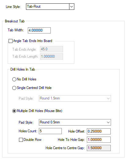
Line Style - choose the line style from the drop down list. This will be used to define the Tab-Rout path in the Panel. Select a line style that has the correct width for the milling tool to be used to cut around the PCB boards in the panel.
Breakout Tab
This section defines the parameters to be used when Create Breakout Tab is used to create breaks in tab-routs. The PCB board is assumed to be on the left side of each tab-rout segment (looking along the segment in the direction of the arrows drawn on it).
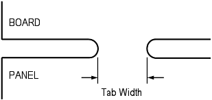
Tab Width - this defines the width of the break in the tab-rout. It is the gap required between the edges of the ends of the tab-rout segments.
The example below shows the Tab Width distance for a straight line breakout tab.
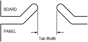
The next example shows how the Tab Width distance is defined when an angle is applied to the tab.
Angle Tab Ends Into Board - Some manufacturers prefer the tab-routs to turn slightly into the board where a breakout tab is required to ensure that the tab breaks inside the board. Check this box if you require angled tab-rout ends. The values define the Angle and the Length as follows:
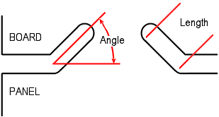
Note: If for some reason you wish the tab to be directed ‘outside’ of the board outline, use an angle greater than 180 degrees.
Drill Holes In Tab
Drill holes can be added in the breakout tab to aid breaking the PCB boards out. Choose one of the three options.
No Drill Holes - Select this if you wish to create a plain breakout tab without any drilled holes.
Single Centred Drill Hole - Select this if you wish to add a single drilled hole to the centre of the tab.
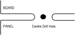
The Pad Style is selected from the drop down list and is taken from the Technology file Pad Styles. Ideally, you should define a style that is “drill only” with no pad land.
Multiple Drill Holes (Mouse Bite) - Select this if you wish to add multiple drill holes (commonly called mouse bites, rat bites or perforation) to your breakout tab. These “nibble” into the board and ensure that the snap line is within the board when broken out from the panel.
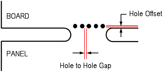
The Pad Style is selected from the drop down list and is taken from the Technology file Pad Styles. Ideally, you should define a style that is a drill only with no ‘pad’ land.
Holes Count - use this to define how many holes will be drilled in the breakout tab. The holes will be positioned in the centre of the tab.
Hole to Hole Gap defines the distance between the drill holes with the spacing taken from the edge of the one drill hole to the edge of the next.
Use a combination of hole count, size of drill and hole to hole spacing to ensure the mouse bites span the tab.
Note: The program will sometimes add more holes than requested when they are on the outside of a tight arc. It does this to try and maintain the same hole to hole distance and tab edge to hole distance that it would have on a straight line tab. If it did not add extra holes the distance from the tab edge to the first hole would be too big to break properly.
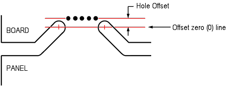
Hole Offset is the amount that the drill holes are ‘indented’ into the board. This value is taken from the inside edge of the tab-rout to the centre of the drill hole. Use this to further ensure the break line in the tab is inside the board. Care should be taken to not move the holes too far into the board where they may clash with items on the PCB. Both a positive and negative value can be used to define the offset.
Note: If you wish the holes to be drilled ‘outside’ the board outline, use a negative offset value. Normally, the number will be positive.
Double Row is used to enable a double row of mouse bites instead of a single row. Use a negative Hole Offset value to move the holes closer together and more towards the centre of the tab-rout line.
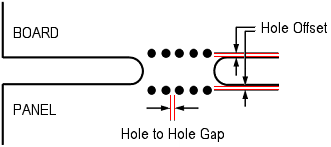
Hole Centre to Centre Gap, this box is greyed out and displays a calculated value using the Hole to Hole Gap plus the Pad Style Drill Hole Diameter.
Special Cases
When the tab has an end angle, the Hole Offset is now taken from the centre of the drill used for the tab. This is shown in the following example.
Related Topics
Create Breakout Tab | Panel Outline Defaults | V-Score Defaults | Design Settings - General | Insert Tab-Rout | Pad Styles | Technology Overview | Properties | Panel PCB Properties | Panel Instance Properties | V-Score Properties