The Import DXF option enables data created in another drawing package and exported in the AutoCAD DXF format, to be imported into PCB, Schematic and Footprint designs. They can be translated into Areas, Boards, Copper, Doc Shapes, Templates and Text. The types of DXF data that are imported are :- Lines, Polylines, Arcs, Circles, Text and Hatching data. All other data types are ignored. If the allowable data types are included in Blocks they will also be translated. The translation of some closed shapes to be cutouts of other closed shapes is also allowed.
Locating this option
Available from: File menu > Import Design Data > choose AutoCAD DXF *.dxf
Importing DXF Data
Import Design Data
You must have a PCB, Schematic or Footprint design open. Select Import Design Data from the File menu. You can then browse for the DXF file that you want to import. You will then be presented with the following dialogs depending on the design type.
Import using drag and drop
As an alternative to using the Import Design Data dialog, simply drag and drop your DXF file from the Explorer dialog straight on top of your PCB and the DXF Import dialog will be displayed:

Mapping Files
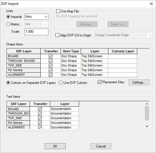
Once you have set up the options on how your data is to be translated, the settings can be saved to a mapping file. If you set up the dialog to use a mapping file then this will be remembered and the same mapping file will be used the next time that you use the import. Use Browse to read in another mapping file. Use Save To to save changes to the mapping to either the same file or to another mapping file.
Units
The data held in the DXF files do not have a units type. Use the Units controls to set up how the data will be interpreted. They can be set up as Imperial or Metric units and you can choose what the base unit type is.
Scale
Once the correct units have been set up, if the imported size is not as required you can use Scale to scale the data to what you want.
Shape Items
For each layer in the DXF file that is used by the allowable data types, an entry will be added to the grid. You can specify if you want to Transfer the shape data on this layer. In PCB designs you can specify what Pulsonix shape type that you want it to be translated to. If it is not a Board item you can specify which design layer you want the shapes to go onto. In Schematics all shapes are translated as Doc Shapes.
You can right click in any cell in the grid to use the Apply To entire Column option from the context menu to copy the value in the current cell to all cells in the same column. Also from the context menu, for any cell in the Layer column, use Copy Shape Layer Map to Text Grid to copy the layers defined for the Shape Items to the layers for the Text Items.
The ends of open shapes will be joined where they align, but if they are too far apart you can join them afterwards using the Join Open Shapes function.
Text Items
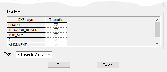
Similarly you can specify which DXF layers that you want to transfer text data from and in PCB designs which design layer that you want the text to go onto.
Cutouts
There are two ways to interpret data that you want to use as cutouts. Use Cutouts on Separate DXF Layers if you want to specify that cutouts on shapes are defined as shapes on a separate DXF layer. Any shapes that fall within the boundary of the shape on the master layer will be added as cutouts of the shape. The shape on the cutout layer will not be translated as a separate shape. A shape defined on a cutout layer can be interpreted as a cutout of shapes on more than one DXF layer. When this option is selected an extra column appears in the grid in which you can pick a DXF layer to use as the associated cutout layer.
Select Use DXF Cutouts if you want islands in hatched DXF shape items to be interpreted as cutouts of the outer shape. The extra Cutouts Layer column will not appear in the grid. Note that in AutoCAD a hatched area can be between edges on separate shapes with any shapes in the middle used as islands. This cannot be interpreted in Pulsonix and will be ignored. Solid hatching in DXF will be interpreted as filled shapes. All other hatching styles will be interpreted as either one hatched style or one cross hatched style.
Schematic Designs
In schematic designs you can select the page that you want the data to be put on to by selecting the Page drop down list.

Footprint Designs
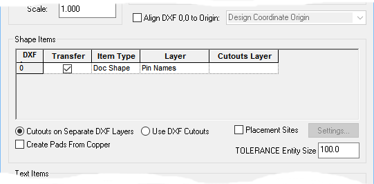
When importing DXF files into Footprints, the dialog is slightly different, it enables special handling of Pads and a tolerance to be defined.

When DXF is imported into Footprint designs, checking the Create Pads From Copper button will treat any closed shape as a Pad. If there is a coincident shape on the top and bottom electrical layers and the shape is not solid then this will be considered as one through hole pad.
The TOLERANCE Entity Size is used to adjust the text size on import. If you have not been instructed to do so, leave this value at the default size that is shown on the dialog.
Placement Sites
When importing into a PCB design, it is possible to generate Placement Sites from ‘crosses’ in the DXF data. Placement Sites are attribute positions in the design, that can be used to ‘snap’ components onto particular locations on the board. If the Placement Sites checkbox is ticked, the design will be examined after import and any crosses (two single segment shapes of the same size that cross at 90 degrees to each other) will be marked with the specified attribute position at the point the lines cross. The layer to be checked for crosses, and the attribute name to use, are specified on the Placement Site Settings dialog. The attribute used should be added to the list of Placement Site attributes in Design Settings.

Align To Origin
Normally, the imported DXF is placed at the coordinates defined in the incoming DXF file. If you prefer, you can choose instead to align the DXF to the Design Coordinate Origin or the Relative Origin (if defined). To do this, simply check the Align DXF 0,0 checkbox, and choose the origin from the dropdown list. This feature can be used for example to load a DXF board outline into an existing design which already has a sheet outline outside where the board needs to go. By placing your relative coordinate origin at the desired location for the board, the incoming DXF data will be shifted to that point.
TOLERANCE Entity Size
For the import of DXF TOLERANCE entities the height of the text cannot be ascertained. Use the edit control to specify the height in the selected units.
Limitations
It should be noted that Pulsonix can only approximate splines using DXF import (or any other import mechanism).
It should also be noted that if your design contains Data Matrix codes using the Special Font type, then you could experience large DXF files.