Assumptions
Pulsonix makes the following assumption: When creating the Footprint in the Footprint Editor, the default solder flow direction is defined as being from left to right (the board will move from right to left [Board Transport Direction] which is the direct opposite of the solder flow direction). The rotation of the footprint created will be classed as 0 degrees at this point.
Footprint Rules Quick Overview
This is a quick summary of the steps required to use the Footprint Rules feature:
- Create or Edit the Footprint for the process required
- Define Attribute(s) on the Footprint (for example, the
attribute and a “Process” attribute to identify the soldering technology and legal rotation) if required - Define the Footprint Rules in your Technology file
- Add new Components to the design and have Pulsonix automatically select the correct footprint and orientation based on the Footprint Rules
- When interactively rotating Components or Mirroring to the other side of the board have the correct footprint and orientation automatically selected based on the Footprint Rules, or use the right click context menu option Auto Footprint to switch to the correct Footprint Rules based footprint at a point you choose
- Run ‘What if’ analysis on the Footprint Rules and report potential changes using the Auto Footprints feature on the Tools menu
- Apply the rules to the design using the Auto Footprints feature on the Tools menu
- Run the Design Rules Check to check the validity of the rules defined
Creating or Editing Footprints for Footprint Rules
If you wish to use Footprint Rules to change the size or shape of a footprint or its pads the set of footprints must be available in the Footprint library in order for the Part to find them. For example, different footprints may be required depending on the rotation and thieving pattern needed.
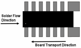
Below is an example of Solder Thieves that have been added to the footprint in the Footprint Editor on pins 4 and 5. The style of thieving will depend on your manufacturing process.

Note that when designing multiple footprints to represent the different arrangement of thieving pads
all other aspects of the footprint, including its orientation, should remain constant across all the
footprints, only the position and size of the thieving pads should vary. Alignment of the footprint to
the Flow Direction in the PCB design is achieved via the
Naming or Renaming Footprints for Footprint Rules
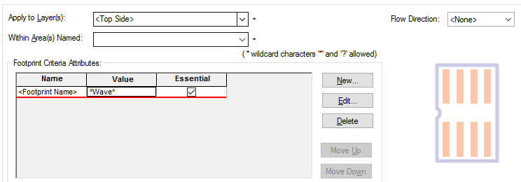
The Footprint Rules dialog can be utilised with the footprint name or additional attributes.
For example, a Part could have alternative footprints for Wave and Reflow use. In this
instance, you might choose your footprint name to reflect these processes, e.g.
SOIC8-Wave and SOIC8-Reflow. The Footprint Rules could then be defined to use
Attributes for Footprint Rules
To apply the Footprint Rules to a design when the
They can also be added directly when editing the footprint in the Footprint Editor using Insert Attribute, but it is important to ensure that Add Attribute To: on the Insert Attribute dialog is set to Design to ensure the attribute will be available for use by Footprint Rules. This may be subsequently checked by displaying Design Properties while still in the Footprint Editor and ensuring that the attribute appears under the Attributes tab.
Using Attributes
The Footprint Criteria Attributes defined within a Footprint Rule are used to identify an
appropriate footprint by matching against the attribute(s) on the footprint. Any design level attribute
attached to a footprint, including the system defined
For example, using the attribute method, if the Name column is set to
Attribute For Flow Direction Alignment
When using Footprint Rules for defining Flow Direction alignment (the rotation), the attribute
Attribute Rule
The
The
For example, the illustration below shows the footprint as created in the Footprint Editor
at zero (0) degrees rotation. It has the attribute values of Reflow and 90
assigned to it for Process and
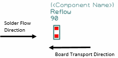
The Footprint Rules dialog could look like the example below. The rules dialog does not need to have the

The illustration below now shows how the Process value rule has been matched and
the

Footprint Rules for Solder Flow Direction
You can use the Footprint Rules for changing footprints to match your soldering process and Flow Direction. A Part definition may contain multiple footprints which are used to represent different arrangement of thieving pads for the various orientations of the footprint pads.
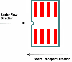
For example, the illustration below shows the footprint in the PCB design, the footprint is at the desired orientation as the board is being designed with the solder Flow Direction Left To Right. However, the footprint is incorrect as it does not have any thieving pads on the footprint for this process.
For our footprint to change to the one based on the Footprint Rules, the rules need to be applied. This is shown below; the Footprint Rules dialog has been defined to use footprints which match *Reflow* in their Process Attribute Value. The new footprint has been created with the correct rotation already applied for this process.
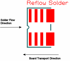
The illustration above now shows how the footprint has changed to the footprint with added thieves on pads
4 and 5. As the
Footprints without the Attribute
Any footprint without a valid
Footprint Rules for size changes
Footprint Rules can also be used to change one or multiple footprint size within a design. This may be useful where one size of footprint is swapped out for another of a smaller size, for example, where the medium or large IPC standard footprint is swapped out for the small standard. This could be done for a whole Layer or Side or for an Area for example.
In the example below, we can swap out all footprints which have an alternative defined in
their Part definition and which have a footprint name containing 0805-med.
Wildcards (*)
have also been used before and after the text string in the Value field to allow a
wide enough search but refined enough to be specific. The Flow Direction has been set to
This scenario could also be used for swapping particular footprints in an Area by entering an Area name in the Within Area(s) Named: box.
Related Topics
Footprint Rules | Auto Footprints | Design Rules Checking | Edit Attributes dialog | Interactive Options | Footprint Rules Override Area | Wildcards