This dialog is used to create or edit a non-standard 3D Package definition. 3D packages are used when STEP models are not available or when you wish to create a custom model.
3D Package definitions can be used to represent a type of component that is not covered by any of the standard package types, or to alter or enhance the appearance of the image that is generated by a pre-defined package.
Locating this option
Available from: Setup menu > Libraries > 3D Packages > New button
Creating a User package
To start creating a new package, you should start from the 3D Package page of the Library Manager 3D Packages dialog, and click the New button.
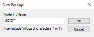
From the dialog, enter the name of the package (which will like other 3D packages be used match the PCB Symbol name of your components) and choose the library in which the new package definition should be saved. Click OK to open the Edit 3D Package dialog.
If the package you want to create is similar to one of the inbuilt package styles, you can first set the Package Style to that inbuilt one and use the controls on the Edit 3D Package dialog to set up the basic appearance of the package. In the example below, you can see we have started from the D9 package in the standard Connector package library. The size and colour of some of the elements have been changed to show a good starting point for your new package.
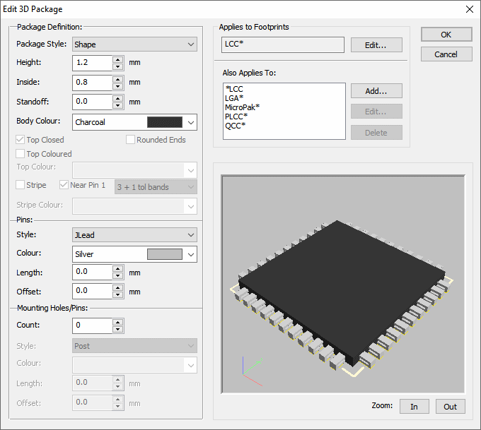
Then change the Style to ‘User’, and you will be offered the option of copying the graphic primitives from the generated inbuilt package to your new User package. This is a good way of getting started with a new package, as it means you do not have to add all the basic elements yourself.
Using the dialog
Here you can see where the editing starts out, the list of graphic primitives is in the top left, below that are the controls used to edit the primitives (more will appear when you select different types of primitive) and to the right is the preview area.
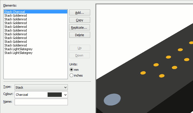
- Element list - select one or more items in this list to modify them
- Add - adds a new element
- Copy - adds a copy of all the selected elements
- Replicate - adds multiple copies of the selected elements
- Delete - removes the selected elements from the list
- Up/Down - used to re-order the elements in the list
Now we can start making the changes to the graphic primitives to achieve the look we are wanting to see. Here you can see we have changed the body colour to blue, and have added two Disks, one inside the other, to represent the hole for the first pin:
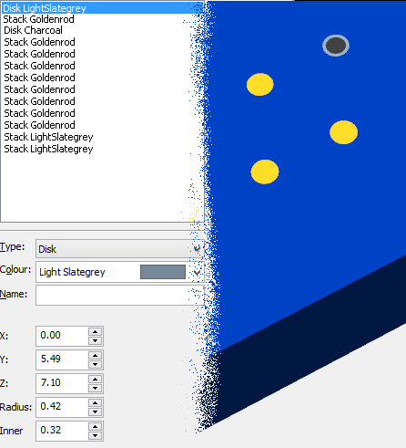
Once in User mode, we can now use Replicate to make some copies of those Disks for the rest of the holes in this row:

Here we can see those new Disks over the rest of the pins in the row:
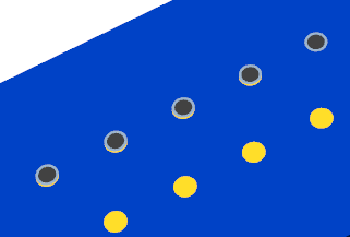
We can however still see the head of the actual pin sticking up through the body, so we select each of the four Stack elements for those, and reduce their Height slightly to take them down below the level of the body. Now we are starting to get the image we want:
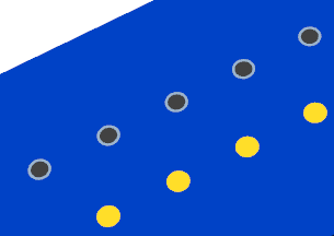
From here on the process can go as far as your imagination and patience will take you. If you are making a large number of edits you can use the Save button occasionally to save your work back to the library, otherwise just click OK when you are finished.
Dialog Controls
Depending on which type of graphic primitive you are editing, the controls shown on the dialog will change to reflect the different values you need to enter to define that primitive.
Coordinates are all defined in millimetres, with the 0,0 point positioned at the origin of the package which is usually the origin of the PCB symbol from which the package was generated. To help you with this, a light coloured ‘cone’ is drawn pointing upwards to indicate where 0,0 is located.
You can change the various values either by typing directly into the edit boxes, or by using the spinner adjacent to each one to alter the values up or down. If you are typing values, the preview will not update immediately, only after a few moments have passed or if you change focus to a different control on the dialog.
The XYZ axis marker in the lower left corner of the preview should help you work out which way is ‘up’ so you can alter the XYZ coordinate values in the right direction.
Box
A Box is a simple rectilinear shape with sides parallel to the axes of the coordinate system, defined by the position of the two opposite corners.

X1, Y1, Z1 : the 3D coordinates of the first corner of the box.
X2, Y2, Z2 : the 3D coordinates of the opposite corner of the box.
Keep Current Size : this will ‘lock together’ the pairs of X, Y and Z coordinates so that you can alter either of them to shift the box up/down, left/right or in/out without it changing size.
Cone
A Cone is a vertical cone.

CX, CY, CZ : the 3D coordinates of the bottom of the cone.
Radius : the radius of the base of the cone.
Height : the overall height.
Disk
A Disk is a flat circular object in the horizontal plane which can have a hole in the middle.

X, Y, Z : the 3D coordinates of the centre of the disk.
Radius : the outer radius of the disk.
Inner : the inner radius to make the hole in the middle, set this to zero if you do not want a hole.
Elbow
An Elbow is a combination of two ‘tubes’, one vertical and one horizontal, with a rounded join where they meet. This is useful for defining things like wire pins on a component where the wire is bent over at an angle.

X, Y, Z : the 3D coordinates of the centre of the bottom of the vertical element.
DX, DY, DZ : the 3D offset of the ‘far end’ of the horizontal element.
Radius : the radius of the tubes.
For example, to achieve an elbow that goes up from the starting point and turns right, you would set DX to the length you desire for the horizontal element, and DY to zero because there is no ‘movement’ in the Y direction as you turn the corner. The value for DZ would specify how far up you want to go before turning the corner. By altering the values of DX and DY you can achieve an elbow that points in any direction.
Hex
A Hex is a simple representation of a hexagonal nut in the horizontal plane which can have a hole in the middle.

X, Y, Z : the 3D coordinates of the centre of the bottom surface of the hex.
Radius : the outer radius of the hex.
Inner : the inner radius to make the hole in the middle, set this to zero if you do not want a hole.
Height : the height of the hex.
Pipe
A Pipe is a horizontal ‘tube’, with optional ‘caps’ on the ends.

CX, CY, CZ : the 3D coordinates of the centre of the pipe.
Radius : the radius of the pipe.
Length : the overall length.
Orient : the angle of rotation, where 0 means horizontal.
Prism
A Prism is a vertically standing triangular prism, formed by defining a right-angled triangle and the height through which this triangle is extruded to make the prism.

X, Y, Z : the 3D coordinates of the corner of the prism.
DX, DZ, DZ : the size of the prism.
Orient : the angle of rotation.
Shape
A Shape is a special type, that holds the shape derived from the original component body for a package that has been generated from one of the standard package types. Although the points and segments that form the basic 2D shape cannot be edited here, the colour can still be altered, as well as the vertical (Z) offset and the height.
Sphere
A Sphere is circular ball of a defined radius.

CX, CY, CZ : the 3D coordinates of the centre of the sphere.
Radius : the radius of the sphere.
Stack
A Stack is a vertical ‘tube’, with optional ‘caps’ on the ends.
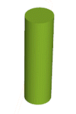
CX, CY, CZ : the 3D coordinates of the bottom of the stack.
Radius : the radius of the stack.
Height : the overall height.