This tool enables you to generate and exchange a group of pads and shapes with a component. It is most often used if you have created your design from a set of Gerber files using the Intelligent Gerber Import option and wish to rebuild the components to assist with future modifications to the design.
The tool will collate selected pads and shapes in the design into a component, either replacing them with a component already in your design or library, or generating a new one from the selected items.
Shortcuts
Default Keys: None
Default Menu: None
Command: Generate Component
Locating this option
Available from: Context menu > Generate Component option
Selecting the items to convert
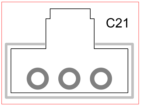
Select the shapes which make up the silkscreen outline and the free pads which will become the footprint pads. Any attached text such as the component Name and Mounting holes can also be included. Other selected items such as tracks and vias will not be affected.
Using Frame Select makes life easier and then deselect those items not required. You can also use the Ctrl and Shift+Select key combinations to select and deselect items. Note that if the data came from an imported Gerber file, then shapes which represent text will simply be shapes, use the Remove Probable Text Shapes check box option on the dialog to automatically delete these.

Once selected, right click and select Generate Component from the context menu.
Note: This option only appears on the right hand context menu for selected pads/shapes and is not available on any other menu. Without the selection of pads/shapes, it will not appear on the context menu.
Using the Generate component dialog
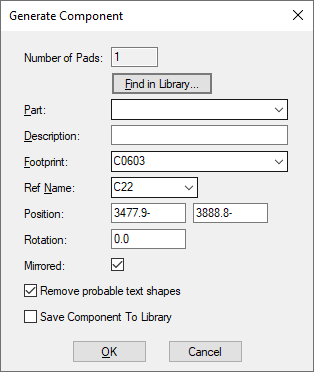
On selection, the following dialog appears:

This dialog is multi purpose; it lets you replace the selected items in your design with a matching library item (component) or lets you create a library item based on your selection. The dialog is split into two halves to facilitate this - Library Item and Design Item.
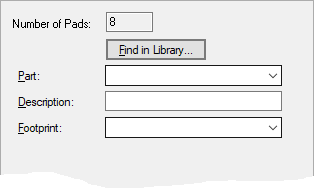
Library Item
This half of the dialog is component selection/generation engine.

Number of Pads: this is confirmation of the number of pads selected in the design. This number does not include any selected Vias or Mounting Holes.
If you wish to use a component (a Part) from your library, use the Find in Library button.
Part: this drop down list will present you with all the components in the design that match the Number of Pads reported above. By selecting one of these components, the pads/shape selection in your design will be replaced with this component.
If you wish to create your own named component, as it may not be available in your design or library, you can type the name you require instead of selecting an existing one. Type the new name into the Part: box.
Description: when creating a new component, you can add a component Description for completeness.
Footprint: this will be the footprint name used by the new component. The drop down list allows you to select an existing footprint from your design or type a new name. If you choose an existing footprint then the pads/shape selection in your design will be replaced by a new component using this existing footprint.
If the data came from a Gerber file, then shapes which look like text will simply be shapes, select the Remove Probable Text Shapes option to automatically delete these. This will use the default text style for symbol names, and causes any selected shape that is ‘small’ (extents smaller than the text style height) to be deleted rather than being included in the new symbol.
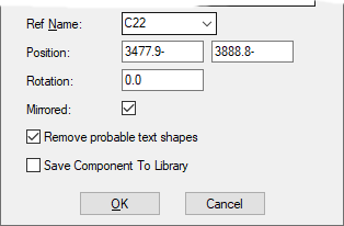
Design Item
This half of the dialog is component positioning portion.

Ref Name: if you wish to create the new component in your design with a specific reference name, R1, R2 etc. then type the name here. The drop down list box will be filled with the Reference Names for components from the Component Bin if you used the Intelligent Gerber BOM Import option or have prepared your design in some other way to place the required components in the Bin.
If you leave the Ref Name field blank, a reference name will automatically be generated for you based on the first letter of the Component name and the next logical number available.
Position: this is initially the lower left corner of the bounding box of the selected pads, so in fact it may even not be the position of an actual pad. You can adjust these coordinates, for example to move the position to the location of a specific pad, but in any case the position is what becomes the origin of the symbol you are creating.
Rotation: the rotation specifies the component instance rotation from the original rotation of the footprint you are creating. So for example if you have two horizontal rows of pads, one above the other, that you are turning into a DIL, but you want the original symbol to be created standing up, you would enter 90 as the angle (symbol standing up, rotated by 90 to get to the position seen on the screen).
Mirrored: this is the state you want to apply to the basic symbol orientation to get the current result for your component instance on the screen. So selecting two bottom side surface mounted pads would assume that this is a mirrored component (and select the check box here) and that the pads and shapes need to be flipped back to get the correct position for the symbol being created (symbols are created on the top side).
Remove Probable Text Shapes: (see above).
Select the Save Component To Library check box which will show the Save Items To Library dialog after the Generate Component dialog closes.
Dialog Usage
There are a number of possible scenarios for which you would use this dialog. For the descriptions below it assumes you have already selected the pads and shapes in your design.
You wish to replace the shapes/pads selected in the design with a component that is in your library
Select the component name using the Find in Library option. The program will convert the selected pads/shapes into a symbol. All other instances using this component will share this definition. You can also optionally define the Ref Name if you wish or one will be allocated for you.
The part is already in the current design, but is undefined (such as when created using Intelligent Gerber Import)
Select the component name from the dropdown list of Reference Names. The program will convert the selected documentation into a footprint outline. All other instances using this part will share this definition. The program will fill in the remaining fields and estimate the position and rotation from the selected pads.
The part exists in a library but is not in the current design.
Use the Find in Library button to find the part. The program will load the part into the current design, it will also estimate the position and rotation from the selected pads.
You wish to replace the shapes/pads selected in the design with a component that is already defined in the current design
Select the component name from the drop down list. The program will fill in the remaining fields and estimate the position and rotation from the selected pads.
You wish to use the shapes/pads selected in the design and create a new library item
You will define the Component details; Component name, Description: (optional), Package: name and the Symbol: name (selected or defined), and a Ref Name: entered (optional), pressing OK will take you onto the Auto Pin Renumber dialog. You must use this to define the order or the pins for your symbol. At the point of selection in the design, these are just free pads in the design with no pad numbers. Once OK is pressed, the new component/symbol is created and the design items selected will be converted.
The component already exists in the Component Bin and you wish to replace the selected items with it
Select the Reference Name from the list (the list will be populated from the names found in the Component Bin). The program will estimate the position and rotation and place the component. Alternatively, do not use the Generate Component option. Just drag the component and let Auto Weld connect it.
The part is not defined in the current design and you wish to define it using the selected items
Type the new part name into the Part field. The program will convert the selected Pads/shapes into a footprint.
Related Topics
Intelligent Gerber Import | Intelligent Gerber BOM Import | Find in Library | Auto Weld | Component Bin | Auto Pin Renumber | Frame Select | Save Items To Library