Use this when editing a Part to define the Part as a DC Source.
Use this on a DC Source component in a schematic design to specify the DC value for the source, used for bias point calculation.
These parts have their Spice Type Built-in Function set to Source - DC Voltage or Source - DC Current.
Shortcuts
Default Keys: F7
Default Menu: Simulation
Command: Edit Spice Value/Model
How To Add A DC Source Component
Once you have a circuit that you wish to simulate, add a DC source device to provide a stimulus for the circuit. There are various ways to add a DC Source device to a Schematic Design:
- From the Parts toolbar, click on the Sources pop-up (battery symbol) to display the Sources toolbar. Click on the Power Supply or DC Current Source buttons.
- From the Parts Browser, click on the Sources category to display a list of sources. Drag the any of the part names mentioned in method 1 above, into the design. Note: This method may not work if you have changed the part categories.
- Use Component from the Insert menu to add Parts with the names mentioned above in method 1, from the SPICE library.
Whichever method is used, you should be presented with a Voltage or Current DC Source component to place in the design.
How To Define A DC Source
In a Schematic Design, select the DC Source device(s) that you wish to change. Press F7 or use the Edit Spice Value/Model option from the Simulation menu, or from the shortcut menu.
From a Parts Library edit the required Part. Press the Edit Spice button on the Details tab. Make sure the Built-in Function is set to Source - DC Voltage or Source - DC Current and press the Edit Value button.
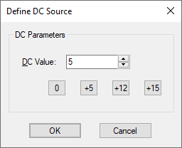
In both cases the following dialog will be displayed:-

Specify the DC value for bias point calculation.
Press on one of the 0, +5, +12, or +15 buttons to quickly use that commonly used value.
Editing Multiple Components
If any of the fields are set to
Related Topics
AC Source | Edit Device Type | PWL Source | Universal Source | Waveform Generator