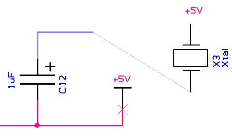
Connect Guides in schematic designs are guidelines to show connectivity to pins where no physical connections have been added or where implied connections exist and have no net names displayed, this excludes Ungated Pins.
As these guides are initially created where they are needed, they would not normally be required. They are used mainly after using the Reverse Engineer option.
Using Connect Guides

Connect Guides are drawn as a thin line starting from a pin that is on a net, but does not have a connection attached and does not display the net name, and ending on the closest node or connection on the same net on the page. If no other node exists on the same page, no guide is drawn.
Displaying On Connect Guides
These guides are initially created where they are needed when you Switch the display of Connect Guides on using the Colours - Others dialog. Once they are visible, they will be created on the fly when you drag a component that has pins that require them. You would not normally create pins that are on a net, but without a connection or net name unless the net name was deleted. These pins are more likely to occur on components that have been created by Reverse Engineer or by Synchronise Designs (when using the PCB design as the master) and placed in the Used section of the Component Bin. When dragged out of the bin the pins that are on nets will have connect guides to other already placed pins on the same net.
Whilst editing the design these guides may disappear completely or no longer end on the absolute closest node, but you can regenerate them by switching the visibility of Connect Guides off and back on again using the Colours dialog.
This option replies on both the Colours - Others and Connect Guides being switched on plus the Show connection to Nearest Node option being enabled within the Options - Edit Connections dialog.
Converting Connect Guides to Connections
All Connect Guides should be converted into connections for the schematic design to be complete. You can double click on a Connect Guide to produce a physical connection manually using the method described in Insert Schematic Connection, or you can use the Route Selected Connections option from the shortcut menu to let the program automatically create the connection.
After being regenerated, Connect Guides can be found on a detailed schematic page using the Find Bar.
Related Topics
Insert Connection | Edit Connection | Colours - Connect Guides | Find Bar | Options - Edit Connections