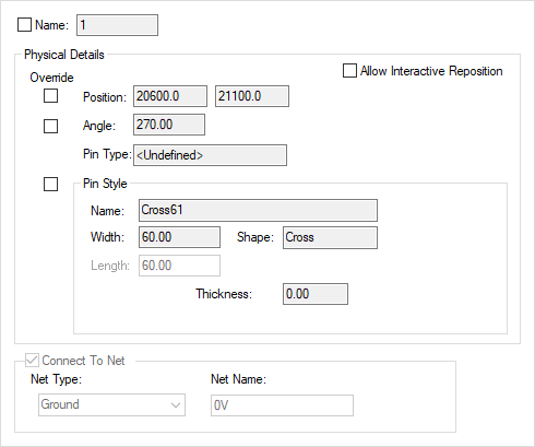
This dialog is displayed when the Properties option is chosen with a Doc Symbol Pin selected.
It shows and allows you to modify properties for the selected Pin.
Shortcuts
Default Keys: I or Alt+Enter
Default Menu: Edit
Command: Properties
Locating this option
Available from: Edit menu > Properties option
Available from: Context menu > Properties option
Available from: Shortcut key > I
Using the Schematic Pin Properties Dialog

Physical Details
Name is the pin number of the selected Pin. Check the control on the left to display the pin name.
Selecting the Allow Interactive Reposition check box to will allow repositioning during interactive operations such as move. With this checked, the pin will be locked against repositioning. When a component with pins is added to the design, all pins will initially have Allow Interactive Reposition switched off, and so they cannot be accidentally moved. By default this is unchecked to not allow interactive repositioning.
Selecting the Allow Implied Junctions check box will allow the automatic creation of junctions between nets on pin locations. With this unchecked, a junction will not be created at that pin point. When a component with pins is added to the design, all pins will initially have Allow Implied junctions switched on, and so the creation of junctions will occur. By default this is checked to allow implied junctions.
Position and Angle display positional information about the Pin. The Position boxes are for reference only but the Angle box is interactive allowing a typed angle value to be used.
Pin type: displays a Pin Type if one has been defined in the Part definition. This cannot be edited in this dialog.
If Pin Style is not checked then the controls display information about the Pin style, or you can alternatively change it to a new Pin Style by defining alternative parameters. This can be done by changing the Width and or Length, or the Thickness size, or the Filled check (if appropriate), or by changing the Shape drop down list. If there is no Pin Style to match these parameters then a new Pin Style will be added with the name that you want to call it.
Connect To Net
Connect To Net allows you to specify that the pin should connect to a net of the given net class type (Power, Ground or Signal, or to a given named net). This is useful, for example, it you wish to create a ground symbol, which should obviously be connected to a Ground net. If the design only contains a single net of the appropriate type, the symbol will be automatically connected to it. If there is more than one net, a dialog offers you the choice. If there is no such net, a dialog offers you the option of creating one. Similarly, for a given net name, if the net exists, the pin is automatically connected.