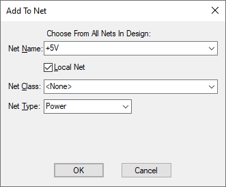
Use this to add an unconnected item to a new or existing net.
In a PCB design, if you want to connect to an existing net, you can also use Insert PCB Connection.
Shortcuts
Default Keys: None
Default Menu: Context Menu
Command: Add To Net
Locating this option
Available from: context menu > Add To Net > option
How To Add An Item To A Net
Using Select Mode or Edit Mode select a Schematics Pin, or a Schematic Symbol Pin, or a PCB Pad, Mounting Hole, Copper Shape or Template. The selected item must not be on a net. Right click to access the shortcut menu and select the Add To Net option.
The Add To Net dialog will be displayed as follows:

Net Name
Selecting a net name from the list compiled from the Net Names in the design’s Technology data, or type a completely new net name.
By selecting an existing net from the list, the item will be added to that net and, if in a PCB design, a connection will be drawn from the item to the nearest item on the existing net.
If typing a new net name you will be asked to confirm adding of that net name to the designs technology data.
When used on a Template or Copper, you can choose to Only List Nets Within The Shape (Meaning nets with an electrical item contained or crossing the shape).
Local Net
This check box is available in Schematic designs and Symbols.
If you have typed in a new net name, the Local Net check box is available. Check the Local Net box to force the net name to only be used in the current scope. The scope is either all pages in the current block instance or all pages in the design top level (i.e. all pages not in a block instance). Alternatively, make it global (i.e available to all pages of the design) by unchecking the Local Net box.
Net Class
You can use the dialog to set the net class that the selected net uses. This can be changed by selecting a name from the list compiled from the Net Classes in the Technology data for the design.
Net Type
A Net Type is an additional parameter on a net that is used to create an additional reference category. It can be useful when creating rules on net items. For more information, see Technology - Net Items.
PCB Safe Mode
If editing a PCB design and you are using the PCB SAFE MODE option from the Design Settings - General dialog, then you will not be able to add a previously unconnected component pad to a net.
Nets in Footprints or Documentation Symbols
It is possible to add Pads and Copper to nets within a footprint or documentation symbol. This creates an internal net within the footprint. When this footprint is used in a design, it will force all pads and copper in the same internal net onto the same net in the PCB. Wires and breakout patterns within a footprint also use these internal nets to ensure the correct connectivity is created in the PCB. The name of the internal net is unimportant and will default to a number (usually a pin number).
Connections within a footprint can be displayed using the Colours, Others option.
You can also create internal connectivity between different nets within a footprint using multiple mapped PCB Pads to the same SCM Pin in a Part using the Parts Editor.
Related Topics
Change Net | Edit Mode | Net Classes | Net Names | Design Settings - PCB Safe Mode | Remove From Net | Select Mode | Split Net | Insert PCB Connection