Use this when editing a Part to define the Part as a Digital Pulse device.
Use this on a Digital Pulse component(s) in a schematic design to change their parameters.
These parts have their Spice Type Built-in Function set to Digital Pulse.
Shortcuts
Default Keys: F7
Default Menu: Simulation
Command: Edit Spice Value/Model
How To Add A Digital Pulse
There are various ways to add a Digital Pulse device to a Schematic Design:
- From the Parts toolbar, click on the Digital pop-up to display the Digital toolbar. Click on the Digital Pulse or Digital Pulse (Open Emitter) buttons.
- From the Parts Browser, click on the Digital category. Then click on the Miscellaneous sub-category to display a list of parts. Drag the Digital Pulse or Digital Pulse (Open Emitter) part names into the design. Note: This method may not work if you have changed the part categories.
- Use Component from the Insert menu to add the Part called Digital Pulse or Digital Pulse (Open Emitter) from the SPICE library.
Whichever method is used, you should be presented with a Digital Pulse component to place in the design.
How To Define A Digital Pulse Parameters
In a Schematic Design, select the Digital Pulse device(s) that you wish to change. Press F7 or use the Edit Spice Value/Model option from the Simulation menu, or from the shortcut menu.
From a Parts Library edit the required Part. Press the Edit Spice button on the Details tab. Make sure the Built-in Function is set to Digital Pulse and press the Edit Definition button.
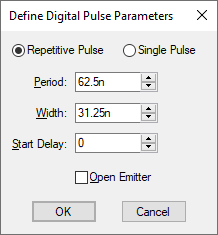
In both cases the following dialog will be displayed:-

Pulse Type
Choose between a repetitive or single pulse.
Period
Enter the period between repetitive pulses. This will be set to zero if a single pulse is chosen.
Width
Enter the pulse width.
Start Delay
Enter the initial delay before the first pulse is supplied.
Open Emitter
Check this box to specify the device to have an open emitter output allowing several pulse sources to be wire OR’ed to create complex pulses.
If Open Emitter is specified a pull down resistor must be connected to the output.
Editing Multiple Components
If any of the fields are set to