The Footprint Wizard Pads page allows you to define all the pad information for your footprint.
Locating this option
Available from: Setup menu > Libraries > PCB Footprints > Wizard button
Using the Footprint Wizard
The exact details you can set up will depend on the type of footprint you have chosen to create.
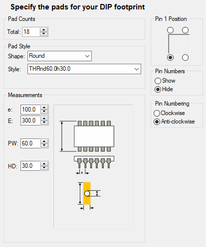
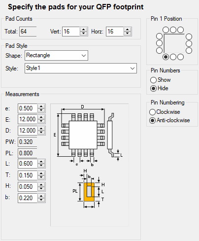
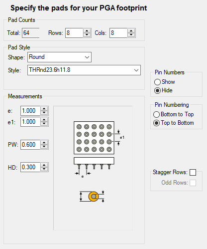
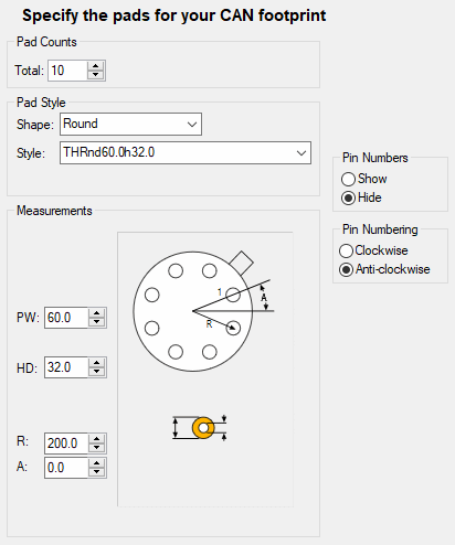
Some examples of the different types are shown below:
For each type of footprint, you will see a diagram showing the dimensions that need to be entered to define the ‘land pattern’ for the symbol. The controls alongside this diagram will be labelled accordingly, and will prompt to you enter only the minimum amount of information needed to construct the symbol. Note that the diagram is only representative of the particular type of footprint being generated and unlike the footprint wizard preview window does not dynamically change with the pad parameters entered.
Generally, for all types, you specify pad sizes, pin numbering information such as the pin one position, whether pin numbers are to be shown and the direction in which the pin numbers will proceed.
The parameter abbreviations are those often used on specification sheets. In general terms, the parameters are as follows:
- E & D - the external dimensions between the outer edges of the leads.
- e & e1 - the distance between lead centres.
- PW & PL - the dimensions of the pad land (pad style), PW is always less than or equal to PL. In some cases these values are derived from the lead, toe and heel lengths.
- L & b - the lead length and the lead thickness.
- T & H - the toe and heel lengths. These specify how much the land is larger than the lead. The heel is also used as the additional distance on each side.
- HD - the drill hole diameter.
- R - on radial footprints, the distance to the pad centres.
- A - on radial footprints, the angle to the first pad.
Footprint Wizard Pads Page for a DIP Footprint
A DIP footprint consists of two rows of pins. The information you will need to specify includes the total number of pins and values to define the pad and row pitch.

Footprint Wizard Pads Page for a QFP Footprint
A QFP footprint had pads on four sides. The information you will need to specify includes the number of vertical and horizontal pads and values to define the vertical and horizontal row pitch as well as the pad pitch.

Footprint Wizard Pads Page for a PGA/BGA Footprint
A PGA/BGA footprint has a grid array of pins. The information you will need to specify includes the number of row and columns, the distance between pins on a row and the distance between rows. In addition, you may optionally offset alternate rows of the grid.
This type of footprint is often difficult to route from, so requires a breakout pattern for each pin. This can be defined next on the breakouts page of the wizard.

Footprint Wizard Pads Page for a CAN Footprint
A CAN footprint consists of a circle of pads. The pads are equally spaced, so you only need to specify the radius of the circle. The position of Pin 1 is given by an angle (0 being centre right).

Related Topics
Footprint Wizard - Start | Footprint Wizard - Technology | Footprint Wizard - Type | Footprint Wizard - Breakouts | Footprint Wizard - Silkscreen | Footprint Wizard - Placement | Footprint Wizard - Finish | Footprint Editor