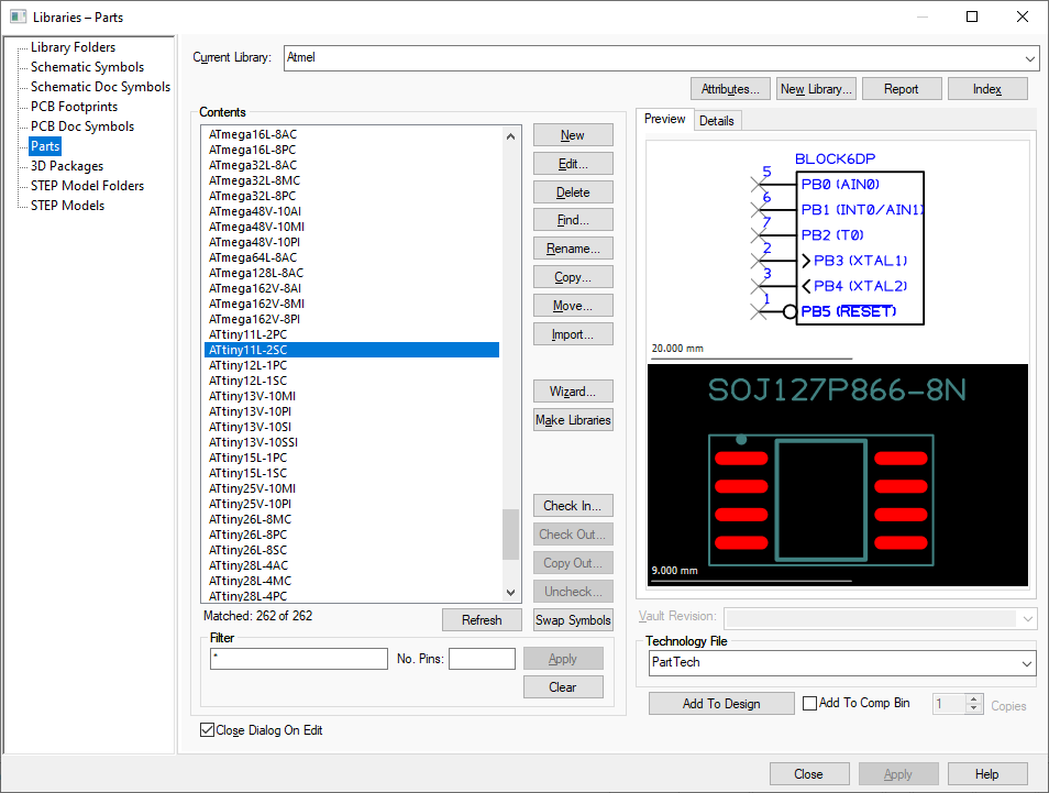
A Library is a file which contains the definitions of a number of Parts, Symbols or 3D packages. Libraries are indexed to allow fast searching and extraction of the relevant data. A library has a type, so only library items of the appropriate type can be stored in a given library. It can theoretically contain any number of items, though in practice it is wise to create a number of libraries each containing related items, this helps both searching and library management.
The Library Manager provides the facilities to create libraries and manage their contents.
Shortcuts
Default Keys: Ctrl+L
Default Menu: Setup
Command: Libraries
Locating this option
Available from: Setup menu > Libraries option
The Library Manager
the Library Manager is used to manage libraries and folders pointing to general libraries and STEP Models.

Buttons on this dialog are described on the Parts Library page for more information.
Using the Libraries option
Libraries are searched in the order specified by the directory order on the Folders tab of the Library Manager. This facility could be used, for example, to enable a user to search both a company standard library set and a local set, where certain parts have an alternative definition. It is also possible to disable individual libraries.
There are seven types of library:
-
Parts - a part contains the mapping between schematic gates and PCB footprints, as well as properties which are common between them. The part is used in both Schematics and PCB, thus ensuring that there is consistency between the two. Parts which have the same mapping between schematic and PCB (but may differ by having different attributes), can be defined in the library as a group.
-
Schematic Symbols - a Schematic symbol or gate is the graphical representation of a part, which you use when designing the schematic. A part may contain a number of gates which may reference the same (homogeneous) or different (heterogeneous) symbols.
-
PCB Footprints - a PCB Footprint symbol is the graphical representation of a part, which you use when designing the PCB. A part may reference a number of footprints as alternative representations, but only one can be in use for a give component.
-
Schematic Documentation Symbols - this is a Schematic only symbol which is not used or referenced by a Part but is used to document your schematic. When used in a schematic design, it does not form part of the netlist. It would be used for items such as page blanks, power or ground symbols, off sheet references, drawing blanks etc. for example.
-
PCB Documentation Symbols - this is a PCB only symbol which is not used or referenced by a Part but is used to document your PCB. This can be used for items such as title blocks, logos, alignment markers, fiducial markers etc. for example.
-
3D Packages - a 3D Package is used as an alternative to a STEP model when one is not available. This will be used in the 3D Viewer and when the STEP 3D mechanical format is exported using the output STEP File option.
-
STEP Models - a STEP model is assigned to a PCB footprint and is used in the 3D Viewer and when the STEP 3D mechanical format is output for the PCB design.
How To Use Parts
Once you have created your Parts and their associated Symbols and Footprints, you can add them to a design. Use Insert Component when editing a Schematic or PCB. The dialog contains a search facility to enable you to find the Part you want.
How To Use Doc Symbols
Documentation Symbols can be used without the need to create a Part. Once created, use the Insert Doc Symbol option to add it to a Schematic or PCB design. These will be used to add extra documentation to your design but without the Doc Symbol appearing on the Parts List.
Related Topics
Using SCM Libraries | Using PCB Libraries | Folders | Part Libraries | SCM Symbol Libraries | PCB Footprint Libraries | SCM Documentation Symbol Libraries | PCB Documentation Symbol Libraries
Insert Component | Insert Doc Symbol | Part Editor | Parts Wizard | Footprint Wizard | 3D Viewer | Output STEP File