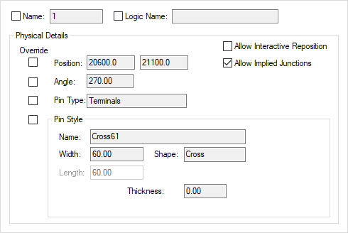
This dialog is displayed when the Properties option is chosen with a pin selected. Pins may be on Schematic symbols, or terminals on Schematic gates.
It shows and allows you to modify properties for the selected pin.
Shortcuts
Default Keys: I or Alt+Enter
Default Menu: Edit
Command: Properties
Locating this option
Available from: Edit menu > Properties option
Available from: Context menu > Properties option
Available from: Shortcut key > I
Using the Schematic Pin Properties Dialog

Name is the pin number of the selected Pin. Check the control on the left to display the pin name in the design.
Logic Name is the logic name of the selected Pin, as defined in the Part. Select the check box to display the logic name in the design.
When in the Symbol Editor, the Logic Name field is editable. By entering a Logic Name here, this value is used as the default when creating a Part which uses this symbol.
A Locked flag appears when editing a pin in a symbol, this enables you to lock the position of the pin to prevent accidental movement.
Physical Details - Override Switches
Selecting the Allow Interactive Reposition check box to will allow repositioning of component pins during interactive operations such as move and align. With this unchecked, the pin will be locked against interactive repositioning. When a component is added to the design, all pins will initially have Allow Interactive Reposition switched off, and so they cannot be accidentally moved in the design.
If editing a pin on a gate or signal reference in a schematic design the Override and Allow Interactive Reposition check boxes will be available. Normally these pins in a design would not have their position and style changed from those defined in the symbol, but occasionally this might be required. Check the appropriate Override boxes to allow changes to the property to their right. Uncheck the Override boxes to return the values to those defined in the symbol.
Allow Implied Junctions - this can be set for an individual pin on the symbol. By unchecking this, no implied junction is drawn regardless of the option set in Design Settings - General - Display Implied Junctions.
Position and Angle display positional information about the Pin. These can be changed by selecting the Override check box and typing new values.
If Override is unchecked the Pin Type displayed is as defined in the Part. Select the Override check box to choose a different local pin type from the drop down list. This list will contain the pin types defined in the design Technology. Pin types are used in Electrical Rule Checking.
No Connect Pins
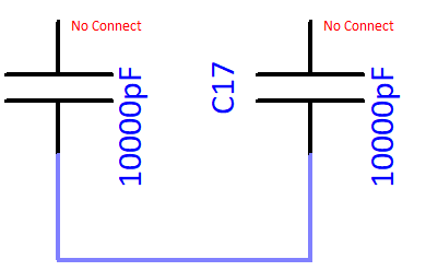
If the Pin Type Override button is checked and No Connect chosen as the type, this will cause the name of the pin type to be substituted into the Net Name attribute for No Connect Pins. Once enabled, a Net Name attribute position will be added to a pin if you make it No Connect and it will be drawn in the highlight colour. This will also work on Component Pins and Block Ports. This control will work in association with the No Connect Pin Highlight colour setting.
It will be displayed like this:

The Pin Style controls display information about the pin style used by the selected pins. If editing a component pin these controls can not be changed unless the Override box is checked. Once enabled, the Name: can be selected from the drop down list box or by interactively typing the Width, or the Length, or the Thickness size, or the Filled check (if appropriate), or by changing the Shape drop down list. If there is no Pin Style to match these parameters then a new Pin Style will be added with the name that you want to call it. For a component pin, uncheck the Override box to return the values to those defined in the symbol.
Pin Networks
If Pin Networks are defined in your technology, then you will be able to add a pin network to the selected component pin by selecting it from the Pin Network control.

If the selected component pin is part of a Pin Network, then the Properties page will show the name of the network, the name of the Master component pad, and any length restriction which may apply. Only the length restriction can be changed through the properties page.

Related Topics
Documentation Symbol Pin Properties | Electrical Rule Check | Part Editor - Gates | Part Editor - Pins | Pin Networks | Pin Styles | Pin Types