The Pulsonix system is able to export design data in IDF format. IDF (Intermediate Data Format) is used for exchanging data between electrical and mechanical systems for use in 3D design.
Shortcuts
Default Keys: None
Default Menu: Output
Command: Output IDF
Locating this option
Available from: Output menu > IDF Output option
How To Use The IDF Export
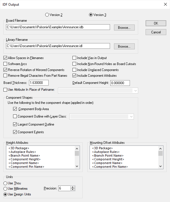
From the Output menu, select the IDF option, the dialog below is displayed:

IDF can be output in either Version 2 or Version 3 formats. Most systems will support Version 3 but if your system does not support this then you can use Version 2. The Mounting Offset data is not used in Version 2.
Board Filename is the name of the file that will hold the board detail part of the IDF data.
Library Filename is the name of the file that will hold the library part of the IDF data.
Allow Spaces in Filenames : uncheck this box to automatically remove spaces from output filenames. Some software including some versions of Pro/Engineer may not be able to handle filenames with spaces in them.
Software Arcs : check this box to have arcs in component outlines represented in the output file as a series of small straight lines. This is necessary when transferring to some software systems that give unpredictable results on rotated and/or mirrored components which have arcs in their outlines.
Reverse Rotation of Mirrored Components : many software packages interpret the orientation of components on the back of the board as the angle you would see when looking at the board from that side. In this case, check this box (the default setting) to have component rotations reversed for mirrored components. If your software package does not interpret rotation of mirrored components in that way, uncheck the box to have component rotations output as defined in the design regardless of their mirrored state.
Remove Illegal Characters From Part Names : check this box to remove characters that are illegal in Part names for some programs, such as Inventor 3D. They will be replaced with an underscore. These characters include: , /, :, *, ?, ”, >, <, |
Include Vias In Output : check this box to include vias in the drill hole section of the output file.
Include Non-Round Holes as Board Cutouts : check this box to output slots in pads, mounting holes and vias (if the Include Vias option is enabled) as cutouts in the board outline.
Include Unplaced Components : check this box to include components from the component bin in the output. Leave unchecked to ignore them.
Include Component Attributes : check this box to includes part attributes in the output file. This can only be for Version 3 formats.
Board Thickness specifies to the mechanical system the thickness of the board. This value is interpreted as current User Units.
Default Component Height specifies the height to be used for components that do not have their own height value. This value is interpreted as current User Units.
Component Shapes : use this section to choose which shape is output for the components in the library data. The chosen shape types will be used in turn for each component until a valid shape is found. If no shape is found and Component Extents is unchecked, no shape will be output.
Component Outline with Layer Class can be used to select which layer class is to be used to choose the component outline shape. The largest closed shape on a layer using the selected layer class is used as the component outline for each component. Choose Largest Component Outline to use the largest closed shape on any non-electrical layer.
You can check the Use Attribute In Place of Partname box if you would like to provide your own part names using an attribute on the component. Select the name of the attribute to be used from the drop-down list. Leave the box unchecked to use the real part name.
Height Attributes is the attribute names to use to find out the height of a component. This
attribute would normally be set up in the Part definition (or within the footprint symbol if using
multiple alternate footprints). Normally, you would use the
Mounting Offset Attributes is the attribute names to use to find out the mounting offset from the board surface of a part. This attribute would normally be set up in the footprint symbol. If a component does not have this attribute setup then a mounting offset of 0 is output. More than one attribute name can used to specify the mounting offset. Select all the attribute names that you want to be considered for the mounting offset. Mounting Offset is not used in Version 2 files.
The Units section provides controls that allow you to choose the units and precision used in the output file.
IDF
IDF data is made up of two separate files, the board data and the library data.
The board data includes :- Board Outlines, Routing Keep In and Keep Out areas, Placement Keep In and Keep Out areas, Via Keep Out areas, Drilled Hole data and Component placement and packaging information. Version 3 also includes documentation text data.
If there are more than one board outline the major one surrounding the rest will be output in the board section and the others will be output in other outlines sections.
The library data contains an entry for each Part/Footprint combination. This data holds the component height and the outline shape to be used.
Pro/Engineer
If you are generating IDF data to use with Pro/Engineer, it may be necessary to uncheck the Allow Spaces in Filenames checkbox as described above. You should also change the default filename extensions to “.emn” and “.emp” instead of “.idl” and “.idb”; you can do this from the Options dialog.