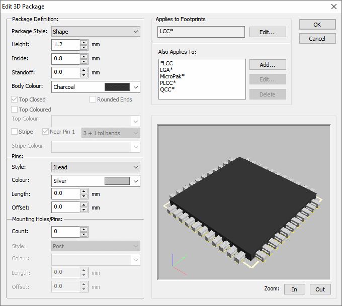
This dialog is used to edit or create a 3D Package definition.
Fields on the dialog allow you to specify which Footprints this package would be used for and the style and other properties of the package.
This page details what each button is used for. For a guide on using this in practical terms, please refer to the 3D Packages help page.
Locating this option
Available from: Setup menu > Libraries > 3D Packages > Edit button
The 3D Package Dialog
The dialog is accessed from the 3D Packages tab of the Libraries dialog. Choose the package you wish to edit, and click the Edit button.
The dialog is divided into several sections, each of which is described below. Depending on the type of package, and other factors like the number of pins, some sections or controls may not be available or appropriate, or may not have any effect on the resulting picture. The best way to see the effects is to try them out and see how the Preview picture changes.

Package Definition
This section defines the basic type of package.

Package Style : The main control in this section, which specifies the general type of the package. Available styles are:
| Axial | Generally two pin through-hole components like resistors and diodes |  |
| Bead | Round ‘bead’ components such as certain LEDs. |  |
| Box | Rectangular components where the box is taken from the overall size of the component |  |
| Can | Vertical cylindrical components such as large capacitors |  |
| Chip | Surface mount chip type components such as chip resistors and capacitors |  |
| DIL | Dual-in-Line components such as DILs, SOICs |  |
| DILswitch | Dual-in-Line switches |  |
| LED | Bead style LED |  |
| LEDdisplay | Dual-in-Line displays |  |
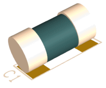
| MELF | MELF style discretes |  |
| Quad | Components (generally surface mount) with pins on all four sides |  |
| Shape | General components where the 3D body shape is derived from the ‘best fit’ shape in the Footprint |  |
| User | A special mode to create User defined shapes |  |
Height : the overall height of the component body.
Inside : for some types, this specifies the amount by which the body should be undersized.
Standoff : the distance between the board surface and the underside of the component body.
Body Colour : the colour of the component body.
Top Closed/Coloured/Colour : some package styles allow the top of the body to be open or closed, and/or set to a different colour to the rest of the body.
Rounded Ends : axial components can have rounded or flat ends to the ‘barrel’ of the body.
Stripe : Axial and Can components can also be given a stripe on the component body. CAN shapes will get a stripe up the side of the body near to pin 1 or pin 2 depending on the pin 1 checkbox. Axial components get a single stripe near one end or the other, except for Resistors and Inductors which will get the correct set of coloured stripes depending on the value of each component. You can choose to use 3 or 4 bands for the value (plus the tolerance band).
Pins
This section specifies how the pins should look.

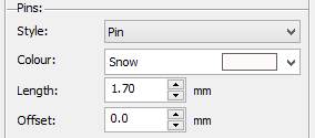
Style : Type of pin. Some of the pin styles are sized and positioned to fit particular styles of package. For example, J-lead, Gullwing and DIL pins will only work for package styles such as DIL and Quad where the pins are around the edge of the component.
Colour : Pin colour
Length : Overall length of pin. This does not have any effect for some types such as J-lead and DIL which measure the pin length automatically from the centre line of the component body.
Offset : Allows the pin to be offset up or down the component.
Mounting Holes/Pins
Where the Footprint has mounting holes, you can choose to display these differently to the normal pins on the footprint, perhaps in a different colour or a different length.

Applies To Footprints
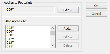
This section specifies the Footprint names to which this package will apply. The first name is the name by which the package will be listed in the Libraries dialog. The other list shows additional Footprint names to which this package will match. Any of these names may contain wildcards, as shown in the example below.

Preview
This section shows a preview of the 3D package you are editing, as long as an appropriate Footprint can be located in the available libraries. Just below the preview is shown the name of the Footprint that is being used.
You can see the effect of changing any of the controls on the dialog straight away. The picture can be rotated in any direction by moving the cursor into the preview window, pressing and holding down the left mouse button and then moving the mouse. Buttons are also provided to allow you to zoom In and Out of the preview picture.
See Also
Library Manager | 3D Packages | 3D Viewer | Creating 3D Packages