The Create Breakout Tabs function allows sections of a panel Tab-Rout to be removed between two cut lines to create a breakout.
The breakout tabs can be removed later using the Remove Breakout Tabs function.
Shortcuts
Default Keys: None
Default Menu: Edit
Command: Create Tab-Rout Breakout Tab
How to Create Tabs
-
Select the Create Breakout Tabs option from the Edit menu. You will notice the cursor change to the “scissors” cursor.
-
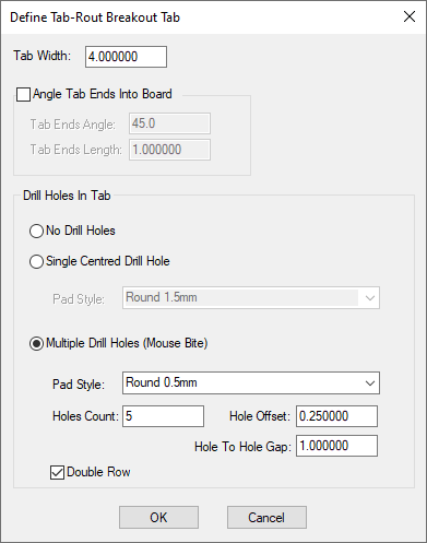
The current tab width is shown on the status bar at the bottom of the screen. To change it, right click the mouse to use the Define Tab-Rout Breakout Tab dialog from the context menu. Type in the required tab width using the current design units. Other parameters for the tab are also presented in this dialog and are explained in more detail at the end of this help page.
-
Left click on a tab-rout segment create a tab by removing a section of the segment. Alternatively, left click in space or drag the cursor to to define the start and end points of a cut line. The position of the second point will be restricted to make the angle of the line a multiple of 45 degrees. All tab-rout shapes that cross the cut line will have a section of the tab width removed from each segment that crosses the line.
Note: this will result in shapes being split into several pieces.
Define Tab-rout Breakout Tabs
The breakout tabs in tab-routs are created with a specified width, can have the tab-rout ends angle into the board, and can contain drill holes to help with breaking the PCB boards out from the panel. To define how you want the tabs to be created right click the mouse and use Define Tab-Rout Breakout Tab from the context menu. The following dialog will be displayed:

The initial values for the tab characteristics available in this dialog are defined in the Defaults section of the Design Settings dialog. See the Tab-Rout Defaults help page for more details about the tab parameters, with diagrams on how they are applied.
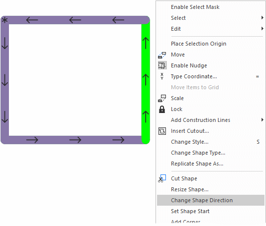
Changing the shape direction
At any point when a Tab shape has been added, you may wish to change the shape direction. When the tab is being cut with the routing tool, it is the leading edge of the tool that makes the cut. This then determines the tab direction and the cut of the tool.
To change the shape direction, with the tab shape selected, select Change Shape Direction from the context menu. The directional arrows on the tab will now change to show the new direction.

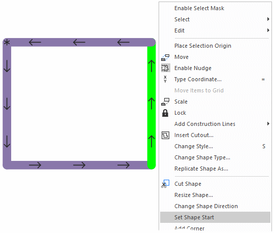
Changing the shape start point
The start point on a shape is indicated with an *. The start point is added at the shape origin when the shape is first added. This can be changed at any point by selecting the shape and choosing Set Shape Start from the context menu.

Related Topics
Insert Panel Outline | Insert Panel Tab-Rout | Insert Panel V-Score | Panel Design | Remove Breakout Tabs | Tab-Rout Defaults