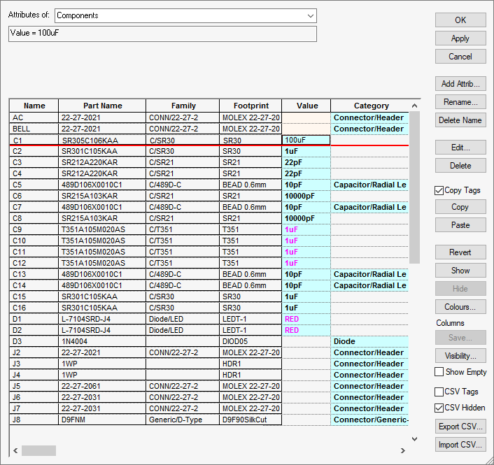
The Attributes option on the Edit menu presents all the attributes in a design (or library) in a spreadsheet style table.
If a design contains selected items, a warning dialog will be presented to ask if all attributes are to be edited, or just attributes on the selected items.
Shortcuts
Default Keys: None
Default Menu: Edit
Command: Attributes
Locating this option
Available from: Edit menu > Attributes option
Using the dialog
At the top of the dialog, choose the type of item from the drop-down list. The types of items available will depend on the type of design or library from which you have invoked this dialog; Components, Differential Pairs, Nets, Pins, Signal Paths or Sub Nets.

To the right-hand side of the dialog are a set of buttons that allow you to modify the attributes. These are described in more detail below.
The remainder of the dialog is occupied by a grid or table of the attributes currently in the design. When using the editor from the Library Manager Parts page, the attribute names in the Technology file are also loaded into the grid for use, even if they do not already exist in any of the parts.
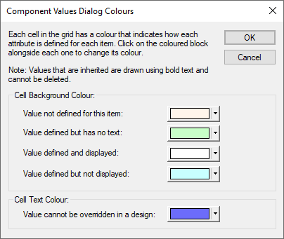
Cells in the grid are coloured depending on their ‘state’, indicating for example whether a particular item has the attribute defined but empty, or defined but hidden, or defined and visible.
The attribute value will be shown using a bold text style if it the value is inherited from another item. For example, if the item is a net and the attribute is actually on the net class, or the item is a component and the attribute is on the part. If the attribute value is changed, it will no longer be shown using a bold style as the item itself will contain an attribute overriding the inherited value.
The text will be a different colour if the value is inherited from a library item and cannot be overridden.
The Edit Attributes dialog can be resized by dragging any of its edges or corners. This allows you to view more attribute information in one go. The size and position of the dialog will be remembered for next time.
Editing attribute values can be done directly in the grid, just like working with a spreadsheet. They can also be modified using the function buttons provided.
Multiple cells in the grid can be selected by holding the left mouse button down and dragging the cursor over a block of cells. This can be used to quickly copy a value to multiple cells using Copy and Paste operations (see below). To select a whole row of cells, left click on the “Name” entry at the start of the row. To select an entire column of cells, left click on the column heading.
The order in which items are displayed in the dialog can also be changed. Right click on the column heading to present a shortcut menu containing the Sort Column option. Use this option to sort the grid by the values in that column. For example, using Sort Column on the “Name” label at the top of the first column will sort the grid by item name (this is the default sort order).
Dialog Buttons
The buttons down the right-hand side of the dialog provide you with tools to edit the attributes and their values. Some buttons may only be enabled if appropriate cells are selected in the grid.

Add Name
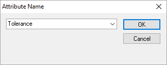
This will add another column (Attribute Name) to the grid, allowing you to create a new attribute name to use for attributes be added to items in the design.

Enter the attribute name to be used for the new column and press OK. An error message will appear if you enter an attribute name that already exists in the grid. Otherwise, a new column will be added to the right hand side of the grid, with the new name shown in the heading row at the top of that column.
Rename
Use this to change the attribute name. A dialog will be presented similar to the Add Name option. Enter the new attribute name and press OK. An error message will appear if you enter an attribute name that already exists in the grid. Otherwise, a new column will be added to the right hand side of the grid, with the new name shown in the heading row at the top of that column. The original column will be removed from the grid unless it contained inherited values.
Delete Name
Use this to remove a column from the grid, thus removing the attribute values for this attribute from all items in the grid. This option will not be available if some of the attribute values are inherited for some of the items in the grid. For example, for a net that has an attribute that is on it’s net class.
Edit
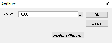
This will open the edit Attributes dialog, allowing you to edit the value of the attribute
in the selected cells. If more than one cell is selected, and the contents of the cells are
different, the attribute value displayed will be the special value "

Edit the Value to contain the text you want, and press OK. The grid will be updated to show the new value in all the selected cells.
If you are editing the values in a library, you will be presented with the No Override check box. Enable this to prevent the value from being changed in PCB and Schematic designs that use this footprint or part. By selecting an attribute name cell in the Edit Attributes dialog, all values in the column will be selected and you can use the Edit dialog to make them all No Override.
Delete / Reset
Depending on what is selected this will either be Delete, Reset or Delete/Reset. Delete will remove the attributes from the selected cells. Reset will reset the selected cells to their inherited values. Delete /Reset will be shown when the selected cells contain both inherited and not inherited values. It will apply the appropriate operation the each selected cell.
Copy Tags
See entry below in the Copy and Paste section:Copy Tags.
Copy and Paste
As well as entering values directly, you can also copy and paste values between cells (or ranges of cells) in the grid. For example, to apply the value in one cell to a number of other cells, start by selecting the first cell and pressing Copy. Then select the other cells (hold the mouse button down to select a range of cells), and press Paste. The same value will be pasted into all the selected cells. If editing attribute values in a PCB or Schematic design, the values will not change if they are marked as No Override in the library item.
It is possible to copy and paste values to and from an external spreadsheet application such as Microsoft Excel perhaps to take advantage of the advanced features of a dedicated spreadsheet application. By default, the Attribute Editor adds embedded tags (<$UNDEF$>, <$VIS$> and <$FIXED$>) in to the copied text to convey additional meaning for the undefined and visible attribute states and these will be visible when pasted in to an external spreadsheet. Text containing these tags can be pasted back into the Attribute Editor and will be interpreted appropriately. Note: the <$FIXED$> tag is only used when editing attributes in libraries, and they correspond to the No Override state of the attribute.
The Copy Tags option controls the copying and pasting of the ‘visible’, ‘fixed’ and ‘undefined’ state information. If you want to copy just the text without the state tags you can uncheck the Copy Tags option. For example, if you want to paste the text into an external application, but if you paste the copied data back into the Attribute Editor any ‘visible’ and ‘undefined’ information is lost. Similarly, unchecking the Copy Tags option before pasting into the Attribute Editor will ignore any of the state tag information.
Note that pasting a completely empty cell value from an external spreadsheet into an Attribute Editor cell will set that attribute to a ‘defined but empty’ state.
Revert
Use this button if you have accidentally modified the wrong cells but do not want to cancel the whole dialog. Pressing Revert will return the selected cells to their original values from the design, leaving other cells untouched. This button will only be enabled if one or more of the selected cells have been modified.
Show and Hide
These two buttons allow you to show or hide the selected attribute(s) in the design.
Colours
This button opens another dialog that allows you to customise the colours used to differentiate between the different states or types of attribute on the main editing dialog.

The colours are retained in the system registry, so that your choice of colours is preserved for future use.
Columns
Save
The Save button allows you to save any changes if the column has been moved left or right using the context menu. If the column has not been moved, this button will remain greyed out.
Visibility…
Set the visibility of the columns. For more information click here
Show Empty
The Show Empty button allows you to show or hide columns in the grid which have no data.
CSV Tags
See below under Export CSV for CSV Tags.
CSV Hidden
When using the Export CSV option (see below), select CSV Hidden to include all hidden columns in the output (this switch is checked by default) and uncheck it to only output columns that are not hidden.
Export CSV
Use this button to export the whole grid to an external CSV format file. The CSV Tags option controls the export of the ‘visible’, ‘fixed’ and ‘undefined’ state information as tags in the cell text. See the Copy and Paste section above for more information on these tags.
Import CSV
Use this button to import the grid data from an external CSV format file. It will only import attributes on items that exist in the design. Any new attribute name columns will be added as new columns on the right side of the grid. The CSV Tags option controls the import of the ‘visible’, ‘fixed’ and ‘undefined’ state information as tags. See the Copy and Paste section above for more information on these tags.
It will not import any changes applied to ‘protected’ columns in the grid, such as ‘Description’ or ‘Part Name’. If the Part Name has been changed in the import CSV, then it will look for that part name within the grid contents and if found, apply the changes. If the part name is not in the grid then it will not make any changes.
Related Topics
Attribute Names | Show Hide Attribute Name Columns | Parts Library Manager