In manual placement of components, you will normally be either be at the stage of translation from schematics into the physical PCB Layout, or will be selecting and manually placing components from the library or component bin.
The description below will provide you with an overview of each of the processes. More detailed descriptions of options within this overview can be obtained from the respective help pages.
Manual Placement After Translation From Schematics
On the Translate to PCB dialog you are presented with the option of Unplaced Components To Bin. If checked, the system will select all the appropriate components from the library and place them in the Component Bin.
You are also presented with the option Show Bin, this will open the component bin automatically after translating to PCB, showing all the components ready to place.

If Unplaced Components To Bin is not checked the components will be placed around the outside of the PCB board profile.
Manual Placement From The Component Bin
With the bin open, a list of components is displayed ready to place. Above the component list, a preview of the footprint selected within the list is also displayed.

To commence placement, click and drag the footprint image or the name from the component bin into the design and place as required. The bin will refresh ready for the next component to be placed.
Manual Placement From Around The Board Outline
If the components have been placed around the board outline, they can be placed in the same way as any other component already placed on the board, or still outside the board outline.
Click and drag the required component into place. The right mouse button shortcut menu will display options available to you during the Move operation.
Component Placement From The Library
To place from the library, select the Insert Component icon from the PCB Toolbar, or Insert Component from the Insert menu.
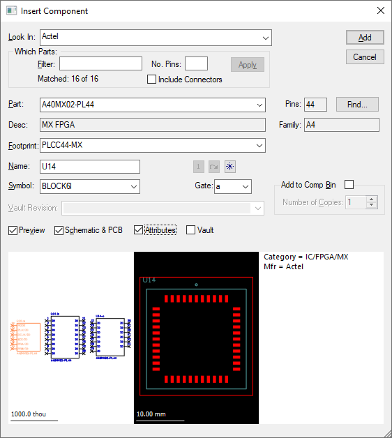
The Insert Component dialog will open:

When the required component is found in the library click Add. If the Add to Comp Bin is checked the selected component will be placed in the bin, or if unchecked will appear on the cursor within the design window. The component can be placed as required with a single click to release it. For more details see Insert Component
Component Placement Grid
When moving components you can select a grid on which they are moved, or no grid at all.
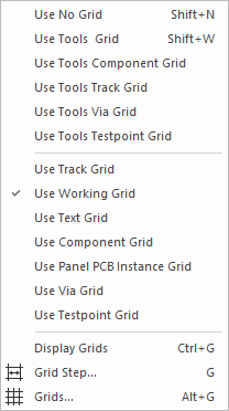
The grid settings can be changed by using the Setup menu and Grids. This option is also available on the shortcut menu as Change Gridor as a shortcut command G during Move.
During Insert Component to the design, the component will snap to the nearest grid point. At the first instance this will be the Working Grid until changed to the Component Grid. Thereafter it will be the Component Grid. For more details on Grids see: Grids
Changing To Gridless or Working Grid Placement
To switch to gridless placement use the Shortcut Key Shift+N. To switch to placement using the Working Grid use the Shortcut Key **Shift+W,**or during component move right click the mouse and select Change Grid. From here you can switch to Gridless, Working grid or Component grid.

Component Placement ‘Push Mode’
With ‘Push Mode’ set the components being moved in the design will ‘push’ existing components to make space and maintain their placement spacing distance. At the same time, ‘Push Mode’ complies at all times with the component spacing rules as defined in the Technology file, see: Technology - Spacing Rules
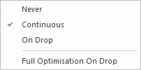
To set Push Mode during the component move processes, right click the mouse and from the shortcut menu select Push Mode. The shortcut menu displays the following selections:

Never means no Push Mode set.
On Drop means pushing of existing components will only take place after the component is ‘dropped’ or finally placed.
Continuous means pushing will take place throughout the placement process if an existing component is encountered.
Again, during the component drag or move processes right click the mouse menu and select Push Direction. A menu opens with the following selections:

Both means pushing will occur in both the horizontal and vertical planes
Horizontal means pushing will only occur in the horizontal plane. If pushing is attempted in the vertical plane then the component will flick out of the way either to the left or right depending on relative component positions
Vertical means pushing will only occur in the vertical plane. If pushing is attempted in the horizontal plane then the component will flick out of the way either upwards or downwards depending on relative component positions
One additional option on Push Mode is ‘Springback’. With springback set the component being pushed will continually attempt to return to it’s original position before the pushing started. This is particularly useful on a tightly packed board where space is at a premium.
To set Springback, during the component drag or move processes right click the mouse menu and click Springback.
Other Features On Manual Placement
Optimisation
Optimisation examines the net connections between components and determines the optimal connection path for each net based on the component positions. Subsequent moving and repositioning of components may of course change this optimal path.
To set Optimisation during the component drag or move processes right click the mouse menu select Optimisation Mode The following options are available.

Never means no net optimisation
On Drop means only optimise after the component is ‘dropped’ or finally positioned.
Continuous means optimisation will be carried out in real time as the component is being moved
If using Continuous or On Drop you can use Full Optimisation On Drop to choose if the optimisation performed at the end uses a quick method (like used for Continuous whilst on the fly), or uses the full optimisation method. The quick method does not fully optimise large nets or connections to power planes.
Optimal Position
This will examine the current position of the component being dragged or moved relative to other connected components and will place the component in the optimal position.
To use Optimal Position during the component drag or move processes right click the mouse menu click Optimal Position.
The system will assess the relative positions of connected components and place the component. This is still is placement mode with the component under cursor control. Once satisfied, a single click will release and place the component.
Optimal Rotation
Optimal Rotation is used to assess the relative connections to other components and rotate the component being moved or dragged so that connection lengths are minimised. It is not combined with Optimal Position as you may wish for all components to be in the same orientation.
To use Optimal Position during the component drag or move processes right click the mouse menu and select Optimal Rotation. For best results this may be used immediately after Optimal Position.
Force Vector
Force Vector is used to give a continual graphic indication of the best or optimal position for a given component while it is being dragged or moved. With Force Vector set an arrow can be seen extending from the component indicating where to place the component. To change the Force Vector arrow type see Force Vector
To set Force Vector during the component drag or move processes right click the mouse menu and select Force Vector
Optimise Selected Nets
Optimise Selected Nets is an option enabling only the selected net(s) to be optimised.
To use Optimise Selected Nets click on the connection and use the Shortcut Keys Shift+L
Rearrange Multiple Items
If you are placing multiple components, mounting holes, pads or vias, that are similar you will be able to use the Rearrange Multiple Items option to place the items in a grid.
Related Topics
Component Bin | Move | Rearrange Multiple Items | Translate to PCB