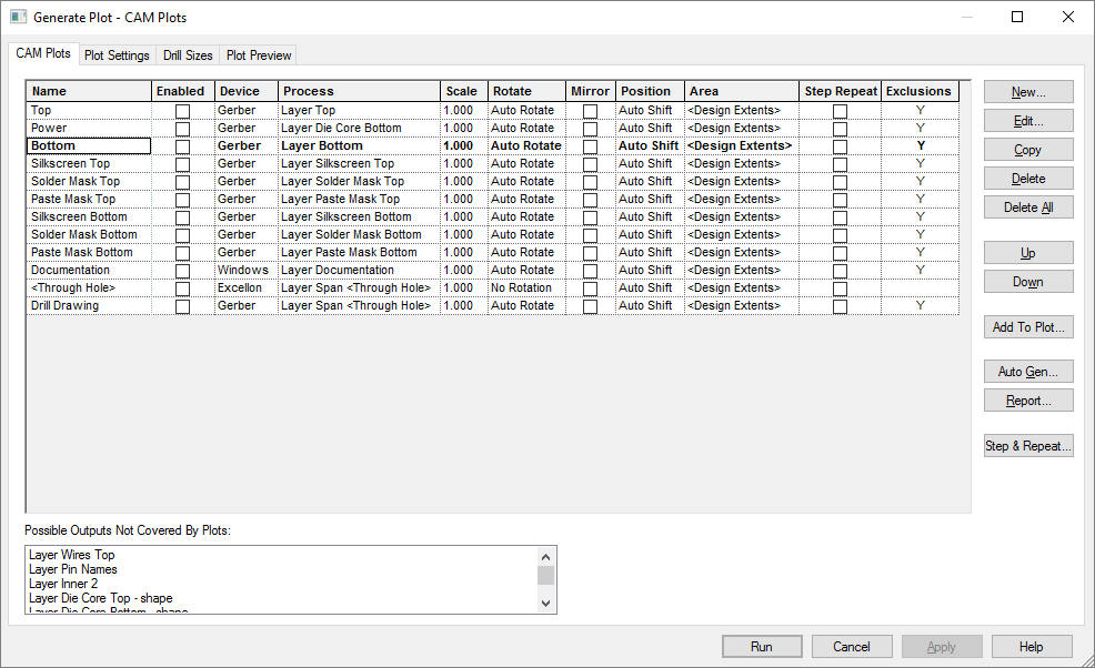
The CAM/Plot dialog is used to create printouts, plots and other CAM outputs. The actual plots that are created are controlled by the rules set up on the CAM Plotspage of the Technology dialog. Before generating any plots you will need to create at least one plot definition. The CAM Plots page from the Technology dialog also appears here on the CAM/Plot dialog for ease of access, to allow you to modify the plots and see the affect of the changes, without having to switch back and forth between dialogs.
Shortcuts
Shortcut: Shift+P
Default Menu: Output
Command: CAM/Plots
Locating this option
Available from: Output menu > CAM/Plots > option
Using the CAM Plots option
If you need to output simple printouts of the design to a Windows printer, you should use the Print option. This option will print out the design as it currently appears on the screen.
The function of each of the tabs on this dialog are summarised below, follow the links for a more detailed description of each one.

CAM Plots
This is the same CAM Plots page as appears on the Technology dialog. All the Plots in your design appear on this page, allowing you to make any corrections necessary without having to switch between dialogs.
Plot Settings
The Plot Settings page shows the current settings for the various output devices available to you, plus other settings that control where the output files are written and so on.
Drill Sizes
The Drill Size Table page allows you to control the drill sizes used in the design and to define an identifier for each size, to be displayed on drill drawing outputs.
Plot Preview
The Plot Preview page shows you a graphical preview of each plot, allowing you to confirm the positioning before actually generating the plots.
Related Topics
CAM Plots | Plot Settings | Drill Size Table | Plot Preview | Print