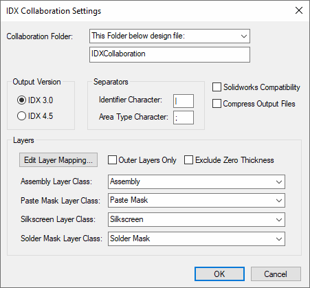
This page describes the options available on the IDX Collaboration Settings dialog.
Locating this option
Available from: 3D Design menu > IDX Collaboration option > Settings button.
Description
On selection from the IDX Collaboration dialog, the IDX Settings dialog is displayed:

Collaboration Folder
This section defines the folder where all collaboration files are stored. This folder is where IDX files are written when they are output.
You can choose from four different settings by selecting from the drop-down list.
- Design Folder : The collaboration folder will be added to the same folder as the design file itself. If the design has not been saved yet, it will be added to the general folder. (See General Folders).
- This Folder : You specify the folder where the collaboration folder will be added. If you type a relative path it will be applied to the current working directory.
- This Folder below design file : you specify a folder name which will be appended to the folder in which the design is stored. For example, if your design is stored in “C:\My Projects\Board 6\Revision 2.pcb”, you can set the folder name to “IDXCollaboration” and all collaboration folders will be added to the folder called “C:\My Projects\Board 6\IDXCollaboration”.
- General Folder : The collaboration folder will be added to the general folder. (See General Folders).
Output Version
This section defines which version of IDX will be used when writing IDX files:
- IDX 3.0 - Widely supported across software that handles IDX collaboration
- IDX 4.5 - Contains improved IDX syntax for more concise and readable IDX files. However, may not be supported by other software.
Separators
These are definable characters used for the internal storage of IDX Identifiers. These characters must be unique and cannot be used elsewhere in the identifier, so it is recommended to use two characters that you will never use.
- Identifier Character - This option is used to separate each individual value in the IDX Identifier. The values are System Scope, Number, Revision, Version and Sequence.
- Area Type Character - In IDX, each area type is defined separately, whereas in Pulsonix a single area can have many types. This character is used to internally separate area types.
SolidWorks Compatibility
Select this option to refine output IDX files so that they are suitable for import into SolidWorks mechanical program.
Compress Output Files
Select this option to compress any output IDX files. The extension of the compressed file will be .idz instead of .idx.
Layers
Edit Layer Mapping
Selecting this option opens the IDX Layer Mapping dialog from where you can map IDX layers to Pulsonix layers.
Outer Layers Only
Select this option to exclude inner layers from being output to IDX files. This helps reduce unnecessary complexity within the IDX file.
Exclude Zero Thickness
Select this option to exclude any layers with zero thickness from being output to IDX files. Some MCAD software, such as SolidWorks, may not allow layers with zero thickness within an IDX file.
Layer Classes
You can choose the Layer Class to use when outputting IDX files using the drop down list box displaying the Layer Class names in your Technology. You can define the following layer classes:
- Assembly
- Paste Mask
- Silkscreen
- Solder Mask