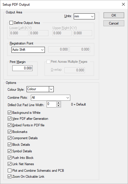
This dialog allows you to change the options used for outputting your design to PDF.
Locating this option
Available from: Output menu > CAM Plots > Plot Settings > Setup - PDF button
Output Area
These fields allow you to configure how the PDF is used for plotting. You can select, from the drop-down list, the type of Units in which you wish to specify the print area values.

Output Area
Normally, PDF does not have a limited output area, it will expand to accommodate the plot. By checking the Define Output Area, you can define how large a page is. Your plot will be cropped to this area. By checking the Print Across Multiple Pages, you can split the output into several pages, each limited to the size defined here. There is an optional Overlap for each page.
Registration Point
This is used for alignment of the printer paper with the Design Position defined in the Plot Wizard for each plot.
Print Margin
This is used to specify the gap around the outside of the plot between the edge of the plot and the edge of the ‘paper’.
Options
Colour Style
Selecting the Colour option will output the data in colour (on a black background). Selecting Black & White forces all colours to be black on a white background. Selecting Grey Scale forces all colours to be converted to a grey scale equivalent. If you intend to print the output to paper you would probably want to for the background colour to be white by checking the Background is White box. Note that if this is not checked for Black & White output, then the output is white on a black background.
Combine Plots:
This option allows you to select how multiple plots are to be printed.
- All - all plots in the plot run into a single document.
- Group(s) - plots are combined if they are within the same group.
- Separately - each PDF plot will be saved as separate documents.
The name of the document will be derived in the usual way, but no plot name will be included. You may want to include the Design Type to ensure PCB and Schematic do not overwrite the same file.
Drilled Out Pad Line Width
This controls the stroke width (line width) of drill holes that do not have their pads drawn. Possible values are between 0 and 10 where 0 is the default stroke width. The higher the value, the thicker the stroke width.
Background is White
If you are likely to print your PDF file, it may be a good idea to force the background colour to be white, otherwise you may waste ink. You should be aware that the other colours do not change (unless the Colour Style is Black & White).
View PDF after generation
Select this option if you want the resulting PDF opened by a PDF reader, such as Adobe Acrobat Reader.
Embed Fonts in PDF file
Select this option if you want the true type fonts to be saved in the PDF file. If this is not selected you rely on the fonts being on other machines that the PDF is viewed on. The main reason that you may not want to select this is to cut down the size of the PDF file.
Bookmarks
Select this option if you want the resulting PDF to have a list of bookmarks to use to jump to a appropriate page, or find a net or component.
Component Details
Select this option if you want each Component to be annotated via popups which give details about the components parts, symbols and attributes. Will list the fitted status for each variant (if any).
Symbol Details
Select this option if you want each Signal Reference, Test Point and Star Point symbols to be annotated via popups which give details about the symbols nets and attributes.
Block Details
In schematic designs, select this option if you want each Block to be annotated via popups which give details about the blocks symbols, attribute and block pins.
Push Into Block
In schematic designs, select this option if you want to be able to select a block in the PDF and push down to the page which has the contents of the block.
Link Net Names
In schematic designs, select this option if you want to be able to select a Net Name in the PDF and jump to the next Sub Net with this net.
Plot and Combine Schematic and PCB
Select this option if you would like to plot and combine PDF plots in the current design and it’s linked design (if applicable). For example, if you have a Schematic design open and select this option, when you begin plotting, another plot dialog displays allowing you to select which PDF plots you would like to plot from the linked PCB design. Once selected and run, these plots will be appended to the end of the document generated by the plots of the Schematic design.
When running a combined plot, the program will either use the same name as the ‘other’ plot or will use the design name defined in the Design Settings, Synchronise, Synchronise Design Name option.
Zoom On Clickable Link
Select this option to enable zoom (as an addition to pan) when clicking on an annotation link.
Related Topics
Plot Wizard | Output CAM | Plot Settings | Design Settings - Synchronise Design Name