Locating this option
Available from: Setup menu > Colours > Others tab
Using the Other Colours Tab
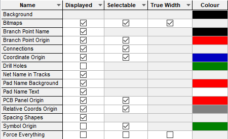
This tab is used to control the colour and visibility of non-layer based items.

- Background Colour defines the colour of the background. Choose the background colour carefully, as it may make other items difficult to see.
- Bitmaps defines the visibility of inserted Bitmaps.
- Branch Point Name defines the colour and visibility for in situ branch point names. These are shown as fixed size text within the branch point and will be automatically hidden when the design view is zoomed out. The font in which they are displayed and zoom level at which they are auto-hidden may be altered in Display Options.
- Branch Point Origin defines the colour and visibility of the Branch Point Origin. Note: In a PCB design the size of the branch point origin displayed is taken from the Branch Point Origin Default value.
- Connections defines the colour and visibility of unrouted connections.
- Coordinate Origin defines the colour and visibility of the Coordinate Origin.
- Drill Holes defines the colour for Drill Holes. When this is not enabled, drill holes will be drawn in the Background colour. Note: the visibility of drill holes will be determined by the settings on the Layer Classes.
- Net Name in Tracks sets the visibility of in situ net names shown within PCB tracks. The net names are fitted to the width of the track and will be automatically hidden when the design view is zoomed out. The font in which they are displayed and zoom level at which they are auto-hidden may be altered in In Place Names Options.
- Pad Name Background allows the background for Pad Name Text (above) or Branch Point Name (below) to be shown in a different colour for improved clarity.
- Pad Name Text defines the colour and visibility for in situ PCB component pad numbers/names. These are shown as fixed size text within a pad and will be automatically hidden when the design view is zoomed out. The font in which they are displayed and zoom level at which they are auto-hidden may be altered in Display Options.
- PCB Panel Origin defines the colour and visibility of the PCB Panel Origin. This is the origin of the PCB design when used in a panel design.
- Relative Coords Origin defines the colour and visibility of the Relative Origin.
- Spacing Shapes allows you to turn off any spacing shapes defined on a pad (they will normally be drawn as a ring around the actual pad land).
- Symbol Origin defines the colour and visibility of the Symbol Origin. Note: In a PCB design the size of the symbol origins displayed on all components is taken from the Symbol Origin Default value.
- Force Everything overrides all other settings in all Colour pages, (except Attributes). Checking Displayed forces everything visible. Checking Selectable makes all displayed items selectable. Checking True Width makes all displayed items true width. This is useful if you want to locate something in the design without changing all the other colour settings. Normally, this row should be all unchecked. Attributes can be Forced on using the Colours - Attributes setting.
Panel Specific Colours
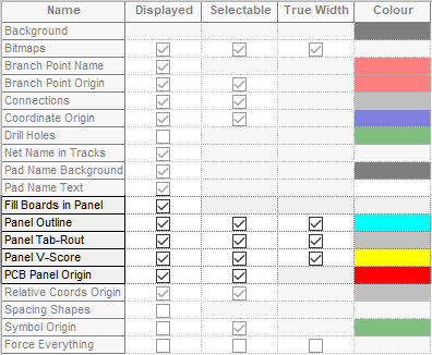
When using the Panel Editor, specific colours relating to panels are also available at the base of the Others dialog:

- Fill Boards in Panel enables the Fill status to be on or off using the Displayed check box.
- Panel Outline panels have their own specific colour, this allows them to be displayed in a unique colour different to that of the board outline and other design items.
- Panel Tab-Rout allows colour for Tab-Routs to be defined.
- Panel V-Score allows colour for V-Score to be defined.
Related Topics
Colours - Overview | Insert Connection | Insert Board | Insert Mounting Hole | Design Settings | Symbol Origin Properties