This page describes how Flexi Bend Line are used.
When to use Board Origins and Flexi Bend Lines
There are two items that effectively do a similar function but are used for two slightly different purposes:
- Board Origins - these are used to add origins to ‘regular’ boards that are not flexi but require positioning in the 3D Preview.
- Flexi Bend Lines - these are used when you wish to fold flexi boards. The lines added indicate where the fold will be plus the angle and bend radius.
When Flexi Bend Lines Cannot Be Used
Board bending cannot be used when the board is being viewed as an Exploded view or as a Single Entity.
Setup and Usage
There are a few items to set up and review before Board bending can be completed.
Adding Bend Lines
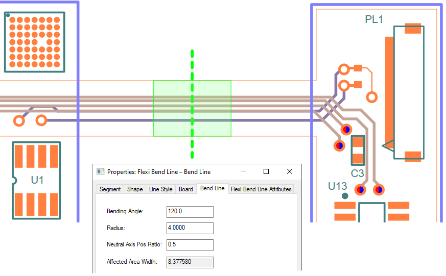
Bend lines are used to define the section of a flexi board that will folded. A bend line is a single segment that cuts through the flexi board, accompanied by a bend region (created from the Affected Area) offset from the main line. This area shows the extents of the fold area, and its size is dependent on the Angle and Radius values that you can define on the bend line.
To add a bend line, use the Insert Flexi Bend Line option on the 3D Design menu. This option is also available on the context menu when a flexi board is selected, but is not for rigid fixed and rigid moving boards. To start adding the bend line, click outside the board and draw the segment so that it slices through the board, and end the segment outside the board. The result should look something like this:

Bend Line Properties
The bend region is defined using an Angle and Radius.
Angle
The Angle defines the angle at which the bend region will be folded - labelled as theta in the diagram below.
Radius
The Radius is defined as the distance away from the bend region that the centre point of the bend is located, labelled as ‘r’ in the diagram below. The radius can be positive or negative, a positive value will fold the bend region in the positive Z direction, and a negative value will fold in the negative Z direction.
Neutral Axis Pos Ratio
The Neutral Axis is a plane within the surface of the shape, such that when the material is bent, the plane does not undergo any tension or compression, and so is the ‘true’ length of the bent shape. See the Flexi Bend Line Properties page has more details of use and the values to set.
Affected Area Width
Altering the Angle and Radius will change the size of the bend region; which can be seeing visually when the offset bend lines move position, or numerically by looking at the Affected Area Width in Flexi Bend Line Properties. This denotes the current width of the bend region.
After setting up the Bending Angle and Radius, your design should look something like this:

Design Rules Checking
There is a dedicated check within the DRC dialog for flexi boards. The Flexi Bend Regions check ensures specific rules are followed.
These rules are explained in detail in the online help under DRC.