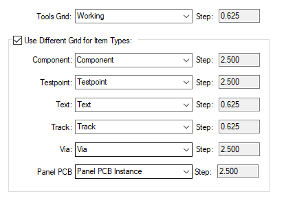
Use this dialog to define which grid will be used by automatic tools which require a grid of the given type
- Component, Testpoint, Text, Track, Via and Panel PCB Item. These grids represent the default system grids.
Shortcuts
Default Keys: Alt+G
Default Menu: Setup Command: Grids
Locating this option
Available from: Setup menu > Grids option Tools tab
How to Use This Dialog

Tools Grid
Use Tools Grid: to display the grid that will be used during automatic operations. The drop down list will reveal a choice of grids. The selected grid will be displayed along with its value next to Step:. The Step: value is taken from the item value on the Grids page.
Use Different Grid for Item Types
For specific items and grids - Component, Testpoint, Text, Track, Via and Working, you can define the grid they will use by selecting the Use Different Grid for Item Types check box. Use the drop down list box to select the grid required for each item type. Next to each grid the Step value is displayed. Uncheck this option to just use a single grid for everything (Tools Grid).
Units
The Units button allows you to locally switch between Metric and Imperial units whilst in this dialog. Once the dialog is closed, the units revert back to the original design units. If switching to different units to the design units, the value typed will be converted when you next enter this page.