Use this to convert straight line segments to arcs, change the angle and direction of existing arcs and to convert arcs back to straight lines.
Can be used on any shape, schematics connection or PCB track segment.
Shortcuts
Default Keys: None
Default Menu: None
Commands:
Arc To Line
Arc Angle 45
Arc Angle 90
Arc Angle 180
Arc To Circle
Arc Edit
Enter Radius
Enter Diameter
Enter Angle
Flip Direction
Locating this option
Available from: Context menu > Arc options
How To Edit Arcs
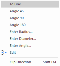
Whilst in Select Mode or Edit Mode, right click the mouse and select Arc from the shortcut menu. The following sub-menu appears:

The sub-menu will have selected the mode that currently matches the selected line’s arc type. Select the required arc mode to alter the selected segment.
Arc To Line
Converts the segment from an arc to a straight line.
Arc Angle 45
Converts the segment to an arc with angle of 45 degrees.
Arc Angle 90
Converts the segment to an arc with angle of 90 degrees.
Arc Angle 180
Converts the segment to a semi-circle (an arc with angle of 180 degrees).
Arc To Circle
Only available if editing a single segment shape that is not a track or bus. Converts the segment from an arc or line to a circle.
Arc Edit
Enters interactive operation to alter the angle of the arc using the mouse. This is explained in more detail in a paragraph below.
Enter Radius
This opens the type coordinate dialog that allows you to specify a precise radius for the arc.
Enter Diameter
This opens the type coordinate dialog that allows you to specify a precise diameter for the arc.
Enter Angle
This opens the type coordinate dialog that allows you to specify a precise angle for the arc.
Flip Direction
Only available if the selected segment is an arc. Swaps the arc direction from clockwise to anti-clockwise and vice-versa.
How To Use Arc Edit
-
Select a segment and use Arc Edit from the shortcut menu as explained above, or Double Click on an existing arc. The arc will become dynamic.
-
Move the mouse to change the arc angle. The arc passes through three points, the segment start, the segment end and the cursor position. This is enough information to define the arc. The arc angle and arc radius are reported to the status bar.
-
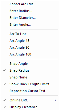
If the arc is in a PCB design, and the shape or track is on an electrical layer, use the shortcut menu options:
Online DRC - to stop the arc from getting too close to other electrical items.
- to show a visible indicator when you are getting close to other electrical items.
-
If you want to put the arc back to a line use the Arc To Line option from the shortcut menu.
-
Left click when the required arc angle is achieved.
Whilst editing an arc, the shortcut menu provides options to help you more accurately define the arc.

Snap Angle
This sets the calculations done whilst moving the arc, to ‘snap’ the arc angle to the nearest degree.
Snap Radius
This sets the calculations done whilst moving the arc, to ‘snap’ the arc radius to the current working grid.
Snap None
This sets the calculations done whilst moving the arc, to allow the arc to be positioned without ‘snapping’ the arc angle or radius.
Latch Mode
Arc Edit can be used in Latched Mode allowing you to edit segments simply by picking them.