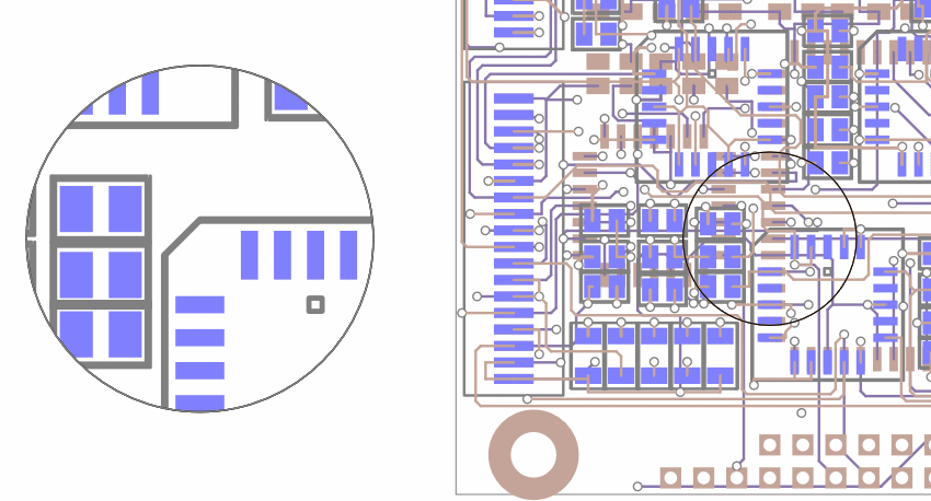
An Embedded View is a ‘live’ image of a defined region of your PCB or Schematic design. Once created, it can be placed anywhere in the same design and will dynamically update whenever design changes are made within the defined region.
Below is an example of an Mirrored and Scaled View

An Embedded View exists as an object in a design in its own right and as such can be manipulated in the same way as any other design shape, including being moved, resized and copied.
It provides an additional view of a region of your design that can optionally be scaled and mirrored and allows layers, colours and visible items to be selected independent of those in the original design.
Shortcuts
Default Keys: None
Default Menu: Insert
Command: Insert Embedded View
Locating this option
Available from: Insert menu > Embedded View option
Embedded View Overview
The overview below runs you through the process, after this are details on how to insert an Embedded View.
- Select Embedded View from the Insert menu.
- Using a Rectangle or Circle Shape, define the area in your design to be used in the View.
- Add details to the Embedded view dialog.
- Position the Embedded View outside your design.
- Press the
key, you are all done. Now you can adjust the view, size, contents, Layers etc. using Properties of the Embedded View.
How To Insert an Embedded View
Use the following procedure to create an Embedded View in a design:
-
Select Embedded View from the Insert menu in a design. The Insert Embedded View cursor will be displayed whilst adding the Embedded View:
-
You may add either a rectangular or circular view; to change, left click and from the popup context menu select or unselect Circular Embedded View.
 ��or��

-
Click or drag the left mouse button to start framing the region of the design to be displayed in the Embedded View, then if adding a circular view follow the procedure for ‘How to insert a Circle’, otherwise follow the procedure for ‘How to insert a Rectangle’. If while framing you wish to restart from a different point you can cancel the current frame and start again by pressing the Esc key or using the Cancel option from the right mouse popup menu. Additional shape editing options such as Define from Centre are also available from the popup menu.
-
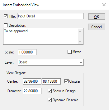
Once defining the Embedded View region is finished the Insert Embedded View dialog will appear.

This dialog displays information about the Embedded View region you have just defined and allows the further details that are required to be entered.
Type in a unique Title and optionally a multi-line Description. You can choose to display either of these as attributes alongside the Embedded View in the design using the adjacent checkboxes. The required Scale factor can be adjusted as required. If you wish to reverse the view check the Mirror option. You can change the Layer on which the Embedded View will be displayed by selecting an alternative from the dropdown list.
NOTE: An Embedded View can only be placed on a non-electrical layer.
The View Region box shows the area of the design that was initially framed and allows the details to be adjusted. You can move the Centre of the region, switch it between Circular or rectangular, or modify its Width and Height or Diameter.
If the Show in Design option is checked, as well as the Embedded View being displayed in the design its View Region will also be shown as a frame. This Embedded View Region, like the Embedded View itself, is a fully functional shape and may be selected, moved and resized. The Dynamic Rescale option determines the effect of changes in size to the Embedded View or its View Region on each other. If unchecked, when either the Embedded View or its View Region is resized the other will simply resize about its centre point to match the new size and the scale factor will remain constant. If checked, when the Embedded View or its View Region is resized, the other, rather than resizing as well, will adjust its scale factor to accommodate the new size thus leaving its own dimensions unchanged as far as a possible. Note however, that when a rectangular Embedded View is being used, changes in shape will inevitably have an affect on the aspect of other.
NOTE: Additional settings such as the specific layers and colours to be displayed within the Embedded View can be set up after it has been inserted by using the Embedded View Properties.
Once the dialog values are correct click the OK button, or alternatively if you wish to abort the Insert Embedded View operation click the Cancel button.
-
After pressing OK, the dialog is removed and the Embedded View frame is displayed in the design at the cursor ready to be positioned.
-
Move the mouse to place the Embedded View at the required position in the design.
-
The right click popup menu provides various options that can be applied while placing the Embedded View including Change Layer which can be used to change the layer on which the Embedded View is placed.
-
Click the left mouse button to finish placing the Embedded View at the required position or select Finish Here from the popup menu. Adding another Embedded View will automatically start.
-
When you have added all the Embedded Views you require, use the Esc key or the Cancel option from the popup menu to exit the Insert Embedded View option.
Embedded View Appearance
A Embedded View is initially created using styles and settings defined in the Embedded View section of the Embedded View Defaults dialog. This dialog defines the layer, line style and text style for the Embedded View, along with parameters that define its initial appearance and behaviour. The line style is used to draw its outline and the text style for its Name and Description attributes if they are displayed in the design. The Text Gap defines the space to be left between the Embedded View outline and the Name and Description attributes when they are initially displayed in the design. The remaining checkboxes provide initial values for options specified during the Insert Embedded View process.
These defaults should be setup before adding your Embedded View. As these values tend not to vary much once they have been setup it is a good idea to set them in your Technology Files ready for use in new designs.
Once an Embedded View has been added to the design and its style and appearance have been set, you can copy these properties for your next Embedded View by selecting the existing one prior to using Insert Embedded View again.
How To Change An Embedded View
Once added, a Embedded View can be moved, resized and flipped like any other shape item. It’s shape however can not be edited except for switching between circular and rectangular.
It may also have its layer, styles, appearance or behaviour altered. To do this, double-click on the Embedded View or select it and right click to display the popup menu. Select the appropriate change menu option or select Properties to display all the properties of the Embedded View for editing. These includes its own set of layers and colours to display within its view.
The Show Viewed Region option, which is similar in effect to the Show in Design option that appears on the Insert Embedded View dialog, is also available from the right click popup menu. If displayed, the Embedded View Region will be shown highlighted whenever the Embedded View itself is selected. Once the Embedded View Region is displayed, it may be selected and manipulated to change the viewed region.
To help locate an Embedded View Region in a densely populated design you can use the Flash Highlights command while the Embedded View is selected, you may assign this command to a shortcut key beforehand or run it from the Run Command facility. Alternatively, by using the extend select feature on the Embedded View you can also select its region, if it is displayed. Subsequently deselecting the Embedded View and using the View Selection option will allow you to zoom to the Embedded View Region. This extend select method can also be applied in reverse to identify an Embedded View when its Region is selected.
If Name or Description of the Embedded View is displayed it will behave and may be manipulated in the same way as any other visible attribute in the design. If the Embedded View is moved, the attribute will move with it. If the attribute is selected on its own it can be repositioned independent of the Embedded View.
The Colours - Doc Shapes dialog allows all Embedded Views to be hidden or set visible as well as defining the colour to be used for drawing their outline.
Pan and Zoom in an Embedded View
It is possible to pan or zoom within a displayed Embedded View and hence change the viewed region or scale. To avoid accidental operation there are extra constraints compared to normal pan and zoom. To pan or zoom using the mouse it is necessary to also hold down the Ctrl key while doing so. To pan or zoom using shortcut keys the Embedded View must first be fully selected.
Related Topics
Embedded View Default Design Settings | Embedded View Properties