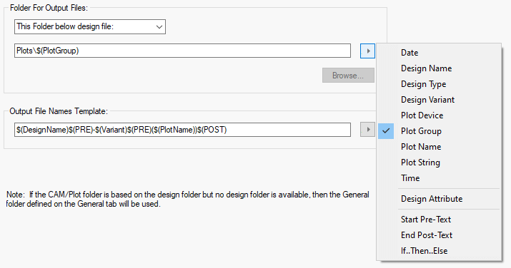
The CAM/Plot Folder dialog is used to specify the folder that plot files are saved to, and how the plot filenames are constructed.
Shortcuts
Default Keys: None
Default Menu: Setup
Command: Folders
Locating this option
Available from: Setup menu > Folders option > CAM Plot page
How To Use The Dialog

Folder For Output Files
This section defines where the CAM and plot files are written when using the Plot function. You can choose from four different settings by selecting from the drop-down list.
- Design Folder : plot files will be written to the same folder as the design file itself. If the design has not been saved yet the file will be written to the general folder. (See General Folders).
- This Folder : you specify the folder where all plot files are written. Either type the required folder path, if you type a relative path it will be applied to the current working directory, or use the Browse… button to use an explorer dialog to choose the folder. You can use the pop-up menu to the right of the folder name box to insert keywords that will be replaced with the correct text when the output file is generated. These keywords are explained in the Output File Names Template section below.
- This Folder below design file : you specify a folder name which will be appended to the folder in which the design is stored. For example, if your design is stored in “C:\My Projects\Board 6\Revision 2.pcb”, you can set the plots folder name to “CAM Output” and all that design’s plot files will be written to the folder called “C:\My Projects\Board 6\CAM Output”. You can use the pop-up menu to the right of the folder name box to insert keywords that will be replaced with the correct text when the output file is generated. These keywords are explained in the Output File Names Template section below.
- General Folder : Use the folder defined in the General Folders dialog. The name of the General folder pre-defined will be shown greyed out as not selectable in the box.
Output File Names Template
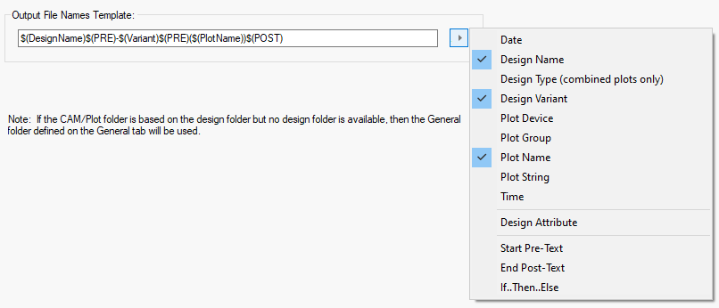
This section defines how the CAM and plot files are constructed. You can type fixed text into the box, and use the drop down menu button to the right of the file name box to insert keywords that will be replaced with the appropriate text when the output file is generated. The first set of keywords, above the menu dividing line, are only inserted once and therefore show a tick on the menu when inserted. Click on an inserted keyword in the menu to remove it from the template. The keywords below the line can be added multiply and so do not show a tick when inserted, and have to be removed by editing the template. The keywords you can use are described below:

-
Design Name : The name of the design the plot is being generated for. If this is the only keyword used and more than one plot is output a number is appended to the end of the file name.
e.g “MyDesign_1.gbr, MyDesign_2.gbr, MyDesign_3.drl”
-
Plot Group : The name of plot group that the plot is in. Each plot can be allocated to a plot group using the Plot Wizard. If the plot being run is not in a plot group this keyword will simply be removed from the file name.
-
Plot Name : The name of the plot being generated. e.g. “Top Electrical”. Note: If the output file contains multiple plots, for PDF output for example, this keyword will not be used, and will be removed from the name.
-
Plot Device : The name of the output device the plot is for, i.e. “Gerber”, “Excellon”, “Windows”, “Pen Plot”, “PDF” and “PDFA”
-
Design Variant : The name of the Variant being plotted. If variants are not being used, or the current variant is set to the master design variant, the keyword will be replaced with “Master Design”.
-
Design Type : The type of the design that the plot is being generated for. This is the default file extension text, so “pcb” for a PCB design and “sch” for a schematic design.
-
Design Type (combined plots only) : This is the same as Design Type above, but the keyword is only replaced with the design type if the file name is for a combined output containing several plots (like for a PDF output).
-
Date and Time - The Date or Time when the file is produced. The format used is the short form of the system time format, but with all special file path characters replaced with a dash character.
-
Design Attribute : Use this to insert the value of a design level attribute into the filename when the plot file is generated. If the attribute does not exist, or its value is empty the keyword will not be used and will be removed from the name. Choosing this keyword from the menu will add ”$(ATTR)” to the template, where “attr_name” must be replaced in the template with the name of the attribute you want to use.
e.g. If the design has an attribute “JOB_NO” with the value “1806”, then ”$(ATTR)” will be replaced with “1808” in the name.
Note: If the attribute value is for a file name rather than a folder, all folder path special characters in the value will be replaced with an underscore character when the template is applied.
-
Start Pre-Text and End Post-Text: Most keywords are obvious, but the ”$(PRE)” and ”$(POST)” keywords are a little different. They are used to add text either side of another optional keyword, but only if it is not blank. So if the optional keyword has a value then the text between the pre-text keyword and the optional keyword will be included and the text between the optional keyword and the post-text keyword will be included. If the optional keyword results in blank text the pre-text and post-text keywords, and all text between them, will be removed from the filename.
For example ”$(PRE)[$(Variant)]$(POST)” will be replaced by “[USA]” for a plot for variant “USA” and will produce nothing for a plot with no variant.
-
If Then Else: There is also a set of advanced keywords that can be used to create conditional folder and filename templates. For example to have completely different CAM Plot file names or folders for each of the different plot device types. See the Plot Settings help for more details on these keywords.
Note: If the template is for a file name rather than a folder, all folder path special characters will be removed from the name when the template is applied.
Plot filename template examples and other options controlling the setup of CAM outputs can be found in the CAM/Plot Plot Settings dialog.
Related Topics
Plot | Choose Folder | Design Backups Folder | General Folders | Backups Options | Library Folders | Plot Settings | Reports Folder