A Signal Path is an ordered set of pins which define a path that can span several nets. Typically, the path links a start and an end pin, passing through one or more passive components. Once a signal path is defined, you can define rules which apply to it. In particular, you may wish to control the overall length of the signal path.
The Net Items page provides an overview of all the net styled items in Pulsonix. This enables you to see the differences and to assess their use for your required usage.
Shortcuts
Menu: Setup
Default Keys: T
Command: Technology
Locating this option
Available from: Setup menu > Technology option > Nets - Signal Paths page
Using the dialog
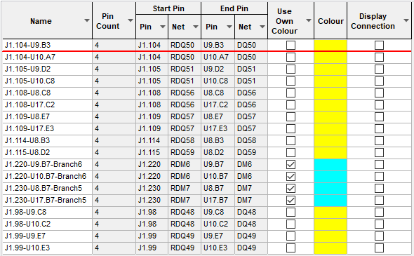
On selection, the Technology dialog opens, select Signal Paths. The existing Signal Paths for the Technology being used will be presented.

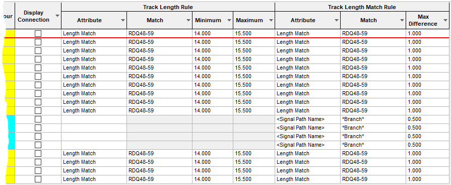
By right clicking in the grid, you can select Advanced View from the context menu. This opens the grid to expose attribute rules and matches:

Navigation
The buttons to the right side of the dialog are used to navigate the grid, the general common buttons are detailed on the Technology Navigation page.
Using the editing pane

Use the New button to create a new Signal Path, this will launch the Create Signal Path dialog. This dialog allows you to select the path which may cross several passive components.
Click here to get more information about Creating Signal Paths.
Name
Once a new Signal Path has been created, the Name can be changed. By default, the name created will be generated based on the start and end pins chosen. You can type any other unique name instead. You can return to the generated name by deleting the existing name.
Reverse Path
The Reverse Path button is used to reverse the order of the pins in the signal path.
Pads In The Signal Path
This box shows all the component names, pins and net names for the selected signal path. You can add extra pins to the path by using the Add box. The Choose Pads dialog is displayed from which to choose valid pads. Once selected these will be added to the Pads In The Signal Path list. Now that additional pads have been added, you can select them and the Remove button will be available.
The Up and Down buttons can be used on newly added pads to re-order them in the list. These buttons will not be available if the signal path order for that net cannot be changed.
Own Colour
Use Own Colour enables you to highlight the signal path using it’s own colour.
Force Display Connections
When Connections are switched off in the design, selecting the Force Display Connections check box will force this signal path to be visible.
Export and Import CSV
Use the Export CSV button to export the data in your design into a CSV format file. Using the Export CSV option will provide you with a formatted template ready for you to edit in your own data.
Use the Import CSV button to import data back into the design using a CSV format file.
The data in the file represents a spreadsheet of dialog contents with the data headings along the top row.
Units
The Units button allows you to locally switch between Metric and Imperial units whilst in this dialog. Once the dialog is closed, the units revert back to the original design units. If switching to different units to the design units, the value typed will be converted when you next enter this page.
Rules and Attributes
Signal Pairs can have attributes, this is primarily so that you can make them match rules. Suitable rules
can also use the in-built
The Rules tab gives you a summary of the rules which currently match the selected signal path. More information about editing these fields can be found on the Rules and Attributes help page.
Related Topics
Technology Overview | Net Items Overview | Create Signal Path | Export CSV | Import CSV