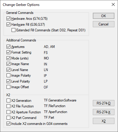
The format of the Gerber plot files you generate may need to be adjusted to match the requirements of your board fabricator. Various aspects of the formatting are controlled by this dialog, which is accessed from the Gerber Setup dialog.
The formatting of coordinates in the output file is controlled by the settings on the Change Format dialog.
Locating this option
Available from: Output menu > CAM Plots > Plot Settings > Setup - Gerber > Change Options page
How to use the Gerber Options dialog
Two groups of switches are included on the dialog, as shown by the picture below. The first group allow you to specify whether or not the Gerber output should assume that hardware support for arc drawing and shape filling is present. The other group allow you to include or exclude certain informative commands that may help the Gerber plotter to correctly interpret your plotter files.

General Commands
Hardware Arcs : If enabled, the Gerber output module will assume that hardware support for arc drawing is present. Arcs will be ‘drawn’ in the output file as actual arcs, using the Gerber ‘G’ commands shown (G74 and G75, technically known as Multi-Quadrant Arc Interpolation). However, if this switch is off, no hardware arc support is assumed, and any arcs in the design will be plotted as a series of small straight lines using the standard move/draw commands.
Hardware Fill : If enabled, the Gerber output module will assume that hardware support for shape filling is present. Filled shapes in the design will be drawn using the Gerber ‘G’ commands shown (G36 and G37). If this switch is off, no hardware fill support is assumed, and filled shapes will be plotted ‘hatched’, using a series of slightly overlapping straight lines. Before generating Gerber files for manufacture, it is well worth checking with your fabricator to see if they can support hardware fill. If your designs have filled shapes, then the resulting plotter files can be considerably larger if hardware fill is not enabled. This can mean that the length of time for plotting (and hence possibly also the cost) is increased.
Extended Fill Commands (Start D02, Repeat D01): Enabling this option will change some of the commands that are output within the pair of commands (G36 and G37) that delimit a hardware filled shape. Firstly, an extra command (D02) will be added as the first command after the G36 command, to move to the start of the shape. Secondly, each “draw” command (D01) will be explicitly written as D01 rather than the usual method of implying D01 as the “last used command”.
This option should only be required if your PCB manufacturer has problems reading your Gerber files. The usual symptom is that an error will be reported when trying to read your files, or that the filled shapes will simply not be filled. This problem is only known to affect a few front end software packages.
The default setting for this switch is “off”, and it should only be switched “on” if the problem described actually occurs when attempting to process or plot your Gerber files.
Additional Commands
These commands are used to control more of the detailed formatting of your output files. Most of these commands appear in the header section of each Gerber file.
Apertures : If enabled, the Gerber output files will include definitions of the apertures required for plotting. This is often referred to as “RS-274-X” or “Extended Gerber”. This means that each plot file is “self-contained” and needs no other listing or table to define the size and shape of the apertures needed for plotting. If this switch is off, then the output file will not contain any aperture commands; in this case you will need to supply the output report file along with your plotter files so that your fabricator can ensure the correct apertures are set up for plotting.
The remainder of the options in this section specify whether or not the corresponding command shown alongside the description will be included in the output files.
The commands labelled as “X2” apply to the X2 revision of the Gerber file format.
RS-274-D, RS-274-X and X2 : pressing one of these buttons will reset the Additional Command switches on this dialog to the state required to conform to these levels/revisions of the Gerber format definition.
Gerber X2 Format
X2 is a revision of the Gerber format that uses additional attributes in the output file to convey more meaning about the file contents.
Commands
File Function : defines the type of data that the file represents. This is determined automatically by the application from the information it can retrieve from the Layer and Layer Class to be plotted in the file. To do this, it uses the layer class type and the name of the class and/or layer, where it will look for certain phrases such as ‘silk’ or ‘paste’ to identify the contents.
Aperture Function : defines the type of design data item for which that aperture is used. This is used to mark the apertures used for things like SMD pads, through pads, vias, tracks, etc., and enables the software that reads the Gerber file to make a more intelligent interpretation of the file contents.
Part Command : this is a title derived from the design itself, and helps to group files together as belonging to the same design without having to rely on the file names.
More detailed information about the Gerber X2 format is discussed on the Gerber X2 page.