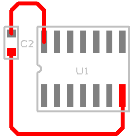
A Pin Network allows you to define additional Components to be connected to a pin. A Pin Network allows you to define a network of components to be connected in series, or in parallel, to a part pin. This is very useful, for example, to specify a bypass capacitor or terminal resistor, to be added to a pin whenever a particular component is added to a schematic.
This dialog allows you to add or edit the names of the pin networks to be used in your Parts and design.

There are two main processes to make the association:
-
For the Part that requires the association - add the Pin Network name on the Pins page of the Part in the Part Editor.
-
The Pin Network itself is defined in the Technology file; define a pin network name and add the Part Name to be used as the secondary Part.
When a component is added to a design, any pin networks defined on the pins are also added to the design. If you have changed a pin network and want to re-apply it to a part, you must use the Replace Pin Networks option on the Part Reload dialog.
Shortcuts
Menu: Setup
Default Keys: T
Command: Technology
Locating this option
Available from: Setup menu > Technology option > Rules - DFM/DFT - Pin Networks page
Using the Pin Networks dialog
On selection, the Technology dialog opens, select Pin Networks. The existing Pin Networks for the Technology being used will be presented.

A Y in the first column indicates that the Pin Network is used in the design.
Navigation
The buttons to the right side of the dialog are used to navigate the grid, the general common buttons are detailed on the Technology Navigation page.
Using the editing pane

Name
A Pin Network must have a unique name within all the Pin Networks in the design This is the string which it is identified by and ties the Pin Network on the Part Pin with the definition in the Technology.
Parts In Network
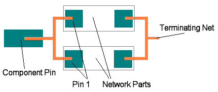
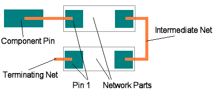
The Parts grid shows the list of parts which will be added (there will often just be a single part). When more than one part is specified the In Parallel check box specifies if the parts are to be connected in parallel or in series with the Component Pin. If in series, a new intermediate net is created between each network part, and they are connected in the order defined in the grid. Normally Pin 1 of the network part is connected closest to the component pin, and Pin 2 connected closest to the Terminating Net. If the polarity is important, you can reverse this by editing the network part.
To add a part to the network, press the Add button, this takes you into the edit network part dialog. The new part is added to the end of the list.
To edit an existing part, select the part in the grid and press the Edit button, this takes you into the edit network part dialog.
In Parallel
Choose if the network is connected in parallel or in series.
Parallel Pin Network

Series Pin Network

Terminating Net
Net Name or Class
The Terminating Net is the net connected to the end of the pin network. You can specify an Net Name or a Net Class for this net, these are used to match with the existing connectivity in the design. So if other pins are already connected to the named net, then the end of the pin network will connect to this net. If a new net is to be created, the net will use the specified Net Class.
End On Pin
The End On Pin check box will cause a prompt to select an existing pin in the design, to be displayed each time a component using this network is added to a schematic. The network will be terminated on the pin selected, the Net Name and Net Class will be used, provided there is no conflict with any existing net on the selected pin.
Units
The Units button allows you to locally switch between Metric and Imperial units whilst in this dialog. Once the dialog is closed, the units revert back to the original design units. If switching to different units to the design units, the value typed will be converted when you next enter this page.
Related Topics
Technology Overview | Using Dialog Grids | Part Edit - Pins | Pin Network Report | Properties - Pad