This dialog allows you to modify properties for the selected Board Bend Line. This is used as a reference line for folding flexi boards in the 3D Preview.
A Board Bend Line is added using the Insert Board Bend Line command.
Shortcuts
Default Keys: I
Command: Properties
Available from: Shortcut key > I
Also available from: Edit menu > Properties option
Also available from: Context menu > Properties option
Using the Board Bend Line Dialog
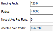
The following Properties - Board Bend Line dialog is displayed:

Bending Angle
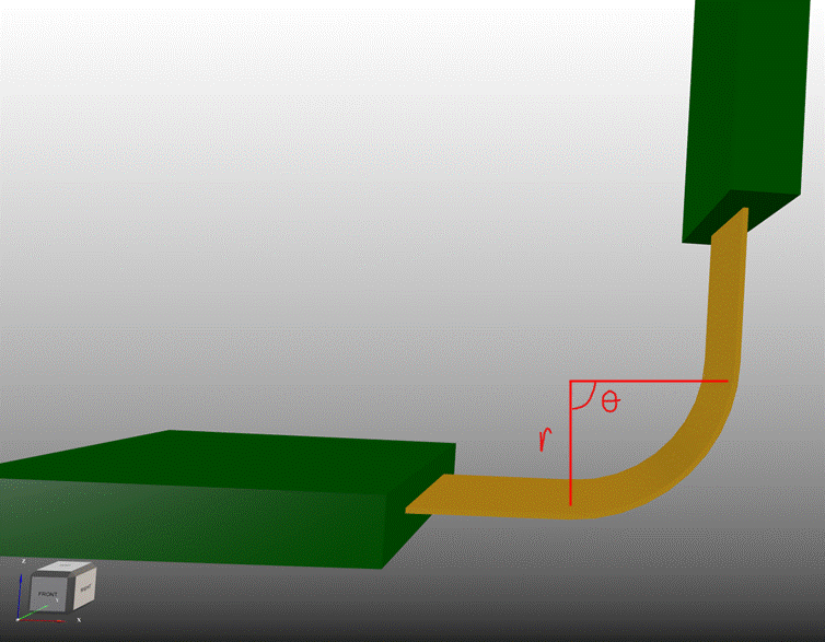
The Bending Angle defines the angle at which the bend region will be folded - labelled as theta in the diagram below. This will be final position as an angle relative to the fixed board.
Radius
The Radius is defined as the distance away from the bend region that the centre point of the bend is located - labelled as r in the diagram below. The radius can be positive or negative, a positive value will fold the bend region in the positive Z direction, and a negative value will fold in the negative Z direction.

Altering the Angle and Radius will change the size of the bend region; which can be seeing visually when the offset bend lines move position, or numerically by looking at the Affected Area Width in Board Bend Line Properties. This denotes the current width of the bend region.
Neutral Axis Pos Ratio
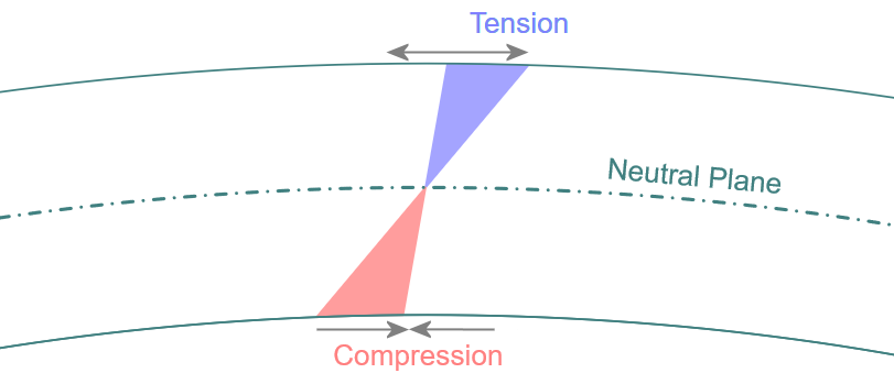
The Neutral Axis is a plane within the surface of the shape, such that when the material is bent, the plane does not undergo any tension or compression, and so is the ‘true’ length of the bent shape. The image below illustrates this:

The position ratio is a real number, from 0 to 1, that defines how far through the flexi board the Neutral Axis is (with 0 being the Outer edge of the bend, and 1 being the inner edge). This ratio alters the size of the bend region that is created. This more accurately calculates the Affected Area Width. The default value for this ratio is 0.5.
By defining this parameter, the visualisation of the bend region Affected Area Width in the 3D Viewer is affected. It is more of a reflection of the true bend that would be seen when the flexi-board is manufactured. This value is not exported in the STEP file.
Affected Area
The Affected Area Width is calculated from the Radius and is shown in the design. Bend lines know where the nearest Fixed board is and do not allow the Affected Area to be inside this fixed board. The Affected Area will be the Flexi Bend Region once in the design.
Bend Regions
Once defined, in the design, the flexi bend lines show the region that will be affected when the bend is applied, this is shown as a translucent region (the same colour as the Bend Line).
Flexi bend regions are visible in the 3D Viewer and are drawn in yellow.
The colour is defaulted to yellow, but can be changed on the 3D Settings Colours page, in the Board section, by changing the Flexi Bend Regions colour. The bend region is shown as a wireframe outline of the region of the board that will be folded.
The bend regions are not output when using the Output STEP file or Output STL options but the fold status is (folded or unfolded).
Related Topics
Insert Board Origin | Board Bending (Overview) | Board Origin | 3D Settings Colours | 3D Viewer | Output STEP