Old versions of Pulsonix-Spice had a different approach to providing saturable magnetic components. Three special parts “Saturable Inductor”, “Saturable 2 Winding Transformer” and “Saturable 3 Winding Transformer” were provided.
These have now been replaced with a single generic saturable part Saturable Transformer which uses a new method that supports an arbitrary number of windings. We recommend changing your designs to use the new method.
If designs have some of the old parts using the old method, they will still work. This help page describes how they work and how to change their model and parameters.
Shortcuts
Default Keys: F7
Default Menu: Simulation
Command: Edit Spice Value/Model
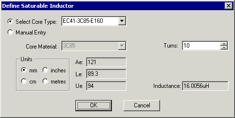
How To Change An Old Saturable Inductor
In a Schematic Design, select the Saturable Inductor device(s) that you wish to change. Press F7 or use the Edit Spice Value/Model option from the Simulation menu, or from the shortcut menu.
The following dialog will be displayed:

Select Core Type
Click on Select Core Type to enable use of standard core types. A number of standard core sets are pre-programmed and can be selected from this list.
Manual Entry
If the model you wish to use is not in the standard core list or if you wish to use a variant with a - say - different air gap, you can manually enter the characteristics by clicking on the Manual Entry button.
Units
Choose which units will be used for the Ae and Le values.
Core Characteristics
The following core values can be obtained from manufacturers data sheets:-
Core Material - Choose from list of standard core materials.
Ae - Enter the effective area, using the Units specified
Le - Enter the effective length, using the Units specified
Ue - Enter the relative permeability
Turns
Enter the number of turns on the winding.
Primary Inductance
This value is calculated from the Ae, Le and Ue values and the number of turns.
How To Change An Old Saturable 2 Winding Transformer
In a Schematic Design, select the Saturable Transformer device(s) that you wish to change. Press F7 or use the Edit Spice Value/Model option from the Simulation menu, or from the shortcut menu.
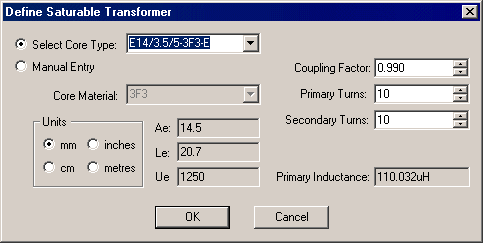
The following dialog will be displayed:

Select Core Type, Manual Entry, Units and Core Characteristics are described in the Saturable Inductor section above.
Coupling Factor
Enter the coupling factor between the two windings. This is the strength of coupling between pairs of windings.
For closely wound windings on ferrite cores this would usually be in the region of 0.98 to 0.99. For separated windings, values of between of between 0.9 and 0.95 are typical. Air gaps tend to reduce coupling.
Primary Turns
Enter the number of turns on the primary winding.
Secondary Turns
Enter the number of turns on the secondary winding.
Primary Inductance
This value is calculated from the Ae, Le and Ue values and the number of turns on the primary winding.
How To Change An Old Saturable 3 Winding Transformer
In a Schematic Design, select the Saturable Transformer device(s) that you wish to change. Press F7 or use the Edit Spice Value/Model option from the Simulation menu, or from the shortcut menu.
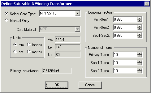
The following dialog will be displayed:

Select Core Type, Manual Entry, Units and Core Characteristics are described in the Saturable Inductor section above.
Coupling Factors
Enter the coupling factors between windings. This is the strength of coupling between pairs of windings.
For closely wound windings on ferrite cores this would usually be in the region of 0.98 to 0.99. For separated windings, values of between of between 0.9 and 0.95 are typical. Air gaps tend to reduce coupling.
Number of Turns
Enter the number of turns on each winding.
Primary Inductance
This value is calculated from the Ae, Le and Ue values and the number of turns on the primary winding.
Old Saturable Device Method
Core Materials
The old models covered a range of ferrite core materials for chokes, and 2 and 3 winding transformers. Different shapes and sizes of cores and winding configurations were accommodated by passing a number of parameters to the model to specify effective dimensions, permeability, coupling factors and number of turns. A number of commonly used core geometries were supplied “pre-programmed” but any can be accommodated by manually entering a few parameters. These parameters can be read directly from manufacturers data sheets.
Notes on Coupling
The coupling factor is the strength of coupling between pairs of windings. For closely wound windings on ferrite cores this would usually be in the region of 0.98 to 0.99. For separated windings, values of between of between 0.9 and 0.95 are typical. Air gaps tend to reduce coupling.
Model Details
The old models for saturable components can be found in the simulator’s model files tx_2.lb, tx_3.lb and ind.lb. The models uses look up tables which relates incremental permeability to magnetising force i.e dB/dH vs H. This is more useful than the more commonly described B vs H as it is dB/dH which determines inductance. For each core material a number of models are supplied for a range of air gaps. Air gaps have the effect of “straightening” the B-H characteristics and gapped cores can be operated at higher flux densities than ungapped cores for a given percentage loss of inductance. For this reason it is not satisfactory to simply scale the values to account for air gaps. The model does not currently handle other core characteristics such as hysteresis or eddy current losses nor does it handle winding artefacts such as resistive losses, skin effect, interwinding capacitance or proximity effect. Some of these will be catered for in future versions of the model. You should note that as far as calculating saturation characteristics is concerned the model assumes that all windings are closely coupled to the core. The specified coupling factor determines the interwinding coupling and also determines the polarity of the core coupling but not the magnitude. In the vast majority of applications this is likely to be satisfactory