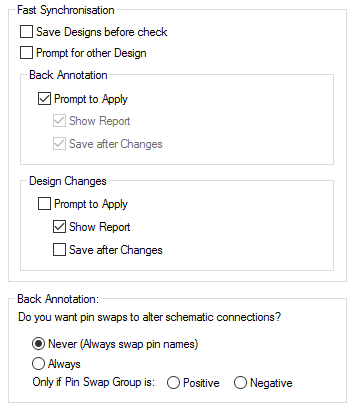
Synchronisation is the process by which design changes are passed between the Schematic and PCB designs. Synchronise Options allow you to control some aspects of this process.
Shortcuts
Default Keys: O
Default Menu: Tools
Command: Options
Locating this option
Available from: Tools menu > Options > Synchronisation page
Using the Synchronisation Tab
All of these options are saved to the registry, so they apply to all the designs you load into the application. For design specific settings see Design Settings - Synchronisation.

Fast Synchronise
Using the Fast Synchronise command is exactly the same as using the Synchronise Designs command, except that you can configure which parts of the process can be done without any user interaction or input.
Save Designs before check
When checked, will cause the modified schematic or PCB designs to be saved before the process begins.
Prompt for other Design
Uncheck this so that the default synchronisation name is used (usually the schematic/PCB counterpart with same name as the current design - see Synchronised Design Name).
Back Annotation
These options allow you to control the Back Annotation process (these are only relevant if there are annotations pending).
Prompt to Apply - If checked, the Back Annotation dialog is shown, otherwise any pending changes are applied without further interaction.
Show Report - If checked and the dialog is not show then the report of pending annotations is shown.
Save after Changes - If check, when annotation changes are applied, the schematic design is automatically saved.
Design Changes
These options allow you to control the Design Change process (these are only relevant if there are differences).
Prompt to Apply - If checked, the dialog is shown, otherwise any pending changes are applied without further interaction.
Show Report - If checked and the dialog is not show then the report of the design changes is shown.
Save after Changes - If check, after changes are applied, the changed design is automatically saved.
Back Annotation
Use this option to set your preference for how Back Annotation applies pin swaps in the schematic design. Choose between two methods, simply exchanging pin names or swapping the connections between the pins (like in PCB). There is also an option for doing a method for only some swap groups, for example where you do not want the pin names to be moved in the schematic for some parts only.
Choose when you would like Back Annotation to use the swap connections method:
- Never - Always exchanges pin names.
- Always - Always swaps connections.
- Positive - Uses the Swap Connections method for pin swap groups that have a positive number.
- Negative - Uses the Swap Connections method for pin swap groups that have a negative number.
Note: Gate Swaps are not affected and will continue to exchange gate modifiers and pin numbers.
Other Options Tabs
| General Options: | Design Backups | Display | Edit Shape | File Extensions | Find | Folders | General | In-Place Names | Macros | Move | Multi-Screen | Pan & Zoom | Resolve Net Names | Select | Tooltips | Warnings |
| PCB Options: | Edit Track | Interaction | Online DRC | Track Length Limits |
| Schematics Options: | Edit Connection | Interaction | Online ERC |
| Footprint Options: | Edit Breakout |
Related Topics
Design Settings - Synchronisation | Back Annotation | Synchronise Designs