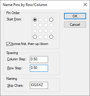
This dialog helps you to assign pin names to grid based components such as BGAs when using the Parts Editor.
Locating this option
Available from: Library Manager option > Parts tab > Context menu on Pins page
Using the dialog

Pin Order
These controls allow you to choose the direction in which the pins will be named. Choose which corner you want to start from, and the direction to go from that corner. With the selection shown above, the bottom left pin would be A1, the pin to its immediate right would be A2, and so on across the bottom row, then the left most pin of row 2 would be B2.
Spacing
These controls allow you to specify the step between the pads that constitute each row and column of your PCB symbol. The initial settings will be automatically determined by examining the arrangement of pads on your symbol, but depending on the order in which the pads were created you may need to adjust these values.
Naming
This control allows you to specify particular characters that will be skipped over when creating the pin names.
The results
Once you have set up the dialog controls and clicked OK, the pin names will be automatically created and displayed in the various pages and views of the parts editor.
The first pin will be named A1, the second A2, and so on until the end of the row or column is reached. The next row or column will start with B1, and so on until all the pins are named.
Where there is a break in the sequence of pins, the pin names for the missing pins are skipped and resume with the pin name appropriate to the row/column that the pins re-commence.