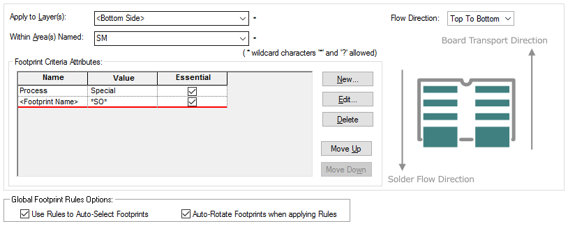
Footprint Rules provide a mechanism for automatically selecting PCB footprints where the Part has multiple footprint alternatives based on defined rules. This may be desirable for a variety of reasons, for example, to provide support for different soldering techniques or technologies. The Footprint Rules allow you to define the footprint type and rotation of the footprint selected for use based on the soldering or manufacturing technology being used.
A Footprint Rule can be thought of as having two facets; the first facet comprises of the Layer and/or Area name, this identifies the side (or area) of the board to which the rule applies. The second facet comprises of the rule to which a footprint must match in order to be valid for use. This information consists of a ‘Flow Direction’ which is used when specifying rules for soldering technologies. It can also consist of attributes for more general criteria. These are made up of an attribute name (with wildcard values) that are used to match against attributes defined on the footprints from the library. The use of wildcard characters when specifying Footprint Rules allows a single rule to cover multiple combinations for example, multiple Areas or wildcard footprint names (i.e. *Wave* or *Reflow*).
Shortcuts
Menu: Setup
Default Keys: T
Command: Technology
Locating this option
Available from: Setup menu > Technology option > Rules - DFM/DFT - Footprint Rules page
Using the Footprint Rules dialog
On selection, the Technology dialog opens, select Footprint Rules . The existing Footprint Rules for the Technology being used will be presented.

If a rule has a single criteria attribute, its details will be shown in
the Name, Value and Essential columns under Footprint
Criteria Attributes. However, if the rule has multiple criteria attributes,
Navigation
The buttons to the right side of the dialog are used to navigate the grid, the general common buttons are detailed on the Technology Navigation page.
Using the editing pane

Assumptions
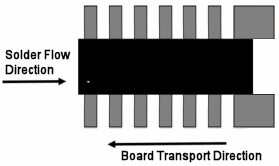
Pulsonix makes the following assumption: When creating the Footprint in the Footprint Editor, the default solder flow direction is defined as being from left to right (the board will move from right to left [Board Transport Direction] which is the direct opposite of the solder flow direction). The rotation of the footprint created will be classed as 0 degrees at this point.

Guide to Footprint Rules
Practical examples and explanations of various Footprint Rules scenarios can be found on the Footprint Rules Details page.
Footprint Rules Order
Footprint Rules are applied to the components in a PCB design in the order they are defined in this table. Successive rules will be compared until a match is found taking into consideration its Layer name and Area name (an area has to be defined as a Footprint Rules override area to be used by this feature). Generally speaking, if you are using this dialog to create Footprint Rules, you will be considering Layer based rules (or Area rules), and will also have a strong appreciation of manufacturing processes.
Use the Up and Down buttons to change the order of the Footprint Rules entries.
It is important to ensure that rules are in the required order and generally the more specific entries are nearer the top of the table and the general definitions using wildcard names and blank fields are at the bottom of the table. This is especially important when using Footprint Rules within a named Area.
Options for Footprint Rules
At the bottom of the dialog are options that effect how the Footprint Rules are applied to components in a PCB design.

Use Rules to Auto-Select Footprints
When this option is checked, the Footprint Rules will automatically select the most appropriate footprint for any component being added to a PCB design, for example, when using the Translate To PCB or Insert Component options.
This option must also be enabled to allow automatic switching of footprints when mirroring or rotating components, although there are additional options in Interactive Options to disable this behaviour.
If this option is not checked, Footprint Rules can still be applied to components after they have been added to a design by using the Auto Footprints feature.
Auto-Rotate Footprints when applying Rules
This option is applicable when the Auto Footprints function is used and ‘Flow Direction’ is being used in the Footprint Rules. Normally, when using ‘Flow Direction’ to support soldering techniques for example, this option would be left unchecked so Footprint Rules will select the footprint appropriate for a component’s existing orientation in the design, in the same way as when a component is interactively mirrored or rotated (if the options allow this).
Checking this option allows the Auto Footprints option to apply a different approach and automatically rotate a component to accommodate a valid footprint. Thus if the component’s existing footprint is valid for its layer (and area, if specified) in the PCB design, but not its orientation, it will be rotated so that it is valid rather than selecting an alternative footprint. Where the component’s existing footprint is completely invalid, a suitable alternative will be selected in precedence order rotating the component if necessary.
For specific details about attributes which effect Footprint Rules (for example Orientation), see the Footprint Rules Details page.
Not Allowing Automatic Changes when using Footprint Rules for a Component
Individual components can be locked so that its footprint does not allow automatic changes by the Footprint Rules option. This can be done using the switch on the Component Properties dialog and setting the Allow Automatic Changes switch on.
Footprint Rules in Design Rules Check
Using the Design Rules Check option, you can check the validity of the Footprint Rules defined. Use the Footprint Rules check box on the dialog.
Related Topics
Technology Overview | Using Dialog Grids | Footprint Rules Details | Auto Footprints | Edit Attributes dialog | Interactive Options | Footprint Rules Override Area | Design Rules Checking