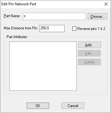
This dialog allows you to define a Pin Network Part. This is the part that is associated when the pin network is used in the design.
Shortcuts
Menu: Setup
Default Keys: T
Command: Technology
Locating this option
Available from: Setup menu > Technology option > Pin Networks tab > New or Edit button
Editing a Pin Network Part

Part Name
You must give the name of the part to use, a network can contain more than one of the same part. The part would normally have exactly 2 pins. At this stage the part does not have to exist in any library, but would obviously need to be created before the Pin Network is used. You can type the part name straight into the edit box or press the Choose (part) button to select an existing part from a library.
Max Distance from Pin
This is used once the schematic using the Pin Network has been converted to a PCB. It specifies the maximum distance the first pin on the network part can be from the component pin using the Pin Network. This value will be shown in the current design units, but when editing this value you can specify the units (e.g. 25mm).
This is useful for checking, for example, that a bypass capacitor is placed close to its associated pin.
You can use the PCB Design Rule Check option to check this rule and create error markers where the actual distance is greater than the maximum specified. This is done by using the Track Length check option in the Nets section of the Design Rule Check dialog.
There is also a Pin Networks Report that can be run to list all the Pin Networks defined in the design’s technology, along with the networks actually used in the design.
An error will be indicated in the report where the components that make up a pin network instance do not match the parts defined for the pin network in the design’s technology.
In a PCB design this report shows the distance each network component is from it’s master pin, shown alongside the required value for the maximum distance allowed and indicating where there is an error.
Reverse pins 1 & 2
The Network Part would normally have pin 1 connected to the component pin and pin 2 connected to the terminating net. When the polarity is important, check this box to reverse the connectivity.
Part Attributes
You can add or override attributes on the Network Part by specifying the values. Press Add to add a new attribute value. Press Edit to edit the selected value, or Delete to delete the selected value (if the library part has a value specified, deleting it from this list will mean that the library value is used).
Related Topics
Technology Overview | Using Dialog Grids | Pin Networks | Pin Network Part Select | Pin Network Report