The Track RF Rules dialog is used within the High Speed Rules option to specify how the track ends are finished and to specify whether track corners will be chamfered and the proportion of chamfer.
The general rule matching mechanism is described here.
Shortcuts
Menu: Setup
Default Keys: T
Command: Technology
Locating this option
Available from: Setup menu > Technology option > Rules - High Speed - Track RF page
Using the Track RF Rules dialog
On selection, the Technology dialog opens, select Track RF . The existing Track RF Rules for the Technology being used will be presented.

Navigation
The buttons to the right side of the dialog are used to navigate the grid, the general common buttons are detailed on the Technology Navigation page.
Using the editing pane

The appropriate track RF rule is found for each net by working down the list of rules until the first match is
found. Hence, the order of the rules is important. A match is when the specified Attribute Name and
Match Value match attributes of a net. So the net must have the given attribute, and it’s value must
wildcard match the value. In particular, you can match the
inbuilt attributes
Back Off Track Ends
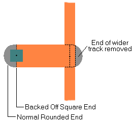
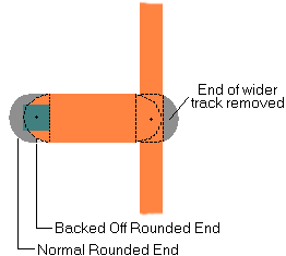
Enabling Back Off Track Ends will cause track ends to be moved back so there is no overshoot. This is only applied to tracks which would otherwise cause an overshoot, and which have sufficient length for the track to be backed off. Design Rule Checking will take the back off into account, allowing tracks to end more closely to other obstacles than would normally be the case. Tracks will be backed off at width changes and T-Junctions, as well as where they terminate at a pad.
You have a choice of how these backed off track ends are finished. They are either Square Track Ends by selecting the check box, or Round Track Ends by leaving it unchecked. The track end style is only available if Back Off Track Ends is enabled. The diagrams below shows the difference in track end styles.
Note that there is a drawing performance penalty when using Backed Off Track Ends.
Note that Teardrops on tracks may need to be re-applied if you change Back Off Track Ends or Square Track Ends.
| Square Ended | Round Ended |
|---|---|
 |  |
Chamfered Track Corners
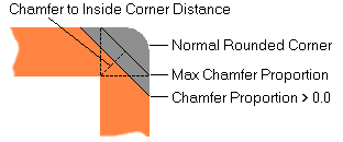
Enabling Chamfered Track Corners causes orthogonal corners to be drawn with a 45 degree chamfer instead of the normal rounded corner. This is particularly useful for high speed signals. Note that the corner is still considered rounded for spatial checking purposes. This gives an over estimate of the space occupied by the chamfered corner. Corners are only chamfered if the track is orthogonal and there is sufficient distance to complete the chamfer before the next corner.

The size of the chamfer is controlled using the Chamfer Proportion. The value gives the distance between the inside corner and the outside chamfer as a proportion of the track width (or the minimum width if the two track segments are different widths). So a value of 0.5 and a track width of 20 thou would cause the distance between the inside corner and the chamfer to be 0.5 x 20 = 10 thou. The value can be between 0.0 and the reciprocal of the square root of two (0.707107).
Maximise
Use the Maximise button to set the maximum value. The maximum value gives a chamfer across the width of the track. A value nearer to 0.0 will lengthen the chamfer and decrease the distance between the chamfer and the inside corner.
Note that there is a drawing performance penalty when using chamfered corners.
Export and Import CSV
Use the Export CSV button to export the data in your PCB design into a CSV format file. Using the Export CSV option will provide you with a formatted template ready for you to edit in your own data.
Use the Import CSV button to import data back into the PCB design using a CSV format file.
The data in the file represents a spreadsheet of dialog contents with the data headings along the top row.
Related Topics
Technology Overview | Using Dialog Grids | Design Rule Check | Export CSV | Import CSV