Pad Styles defines the Pad shapes that may be used in a design.
Shortcuts
Menu: Setup
Default Keys: T
Command: Technology
Locating this option
Available from: Setup menu > Technology option > Pad Styles tab
Using the Pad Styles dialog
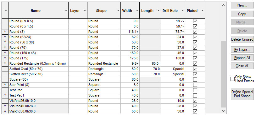
From the Technology dialog, select the Pad Styles tab. Any existing Pad Styles for the Technology being used will be presented.

In the grid, the Y before the pad style Name shows that the style is used in the design. The used status is also indicated for the selected style in the editing pane with the Used box showing a tick. A style which is referenced in the Design Settings defaults is considered used.
Navigation
The buttons to the right side of the dialog are used to navigate the grid, these are detailed on the Technology Navigation page.
Use the Merge button to access the Merge Styles page from where you can merge selected styles.
The By Layer button is used to provide exceptions to the pad style definition on different layers. Use it to define a different shape for a pad style on specific design layers.
Use the Expand All button to expand (unfold) all the By Layer exceptions in the list. Similarly, Close All will close all the By Layer exceptions.
Define Special Pad Shape
The Define Special Pad Shape button enables you to edit the currently selected pad style and create custom pad shapes. When you press the button, the User Defined Pad Shape editor will open to allow you to interactively edit the drill and pad shapes. You will need to leave the technology dialog in order to do this.
Using the editing pane

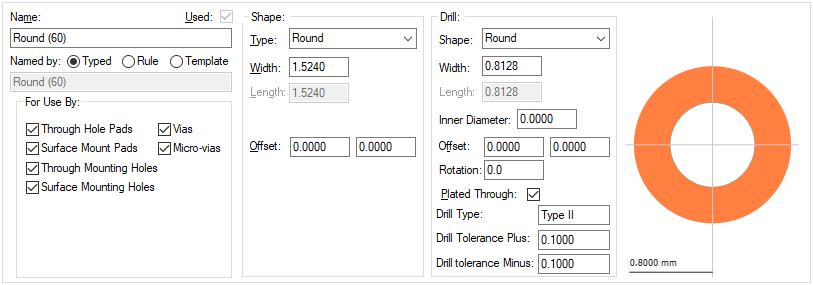
Name
The Name of the style. It is recommended that a meaningful name is used, one that suitably describes the style when you choose it from a list in the design at time of use.
Named by
When New is used the initial style being added is taken from one of three states using the Named by: radio buttons.
Typed - the style has an explicit name.
Rule - this will use the rule defined in the Technology Pad Style Naming rules dialog. The name of the style is derived using the first matching rule, this is displayed in the greyed box below it. Once an item is defined as using a rule, if the rule then changes, it will change the style name.
Template - you can define the template explicitly for this style, you can use any of the fields available for Pad Style Naming.
Once the name has been entered, other properties on this page define the overall look and shape of the pad style:
Used
The Used field will be checked if the current style is used in the design. This is for information only.
For Use By
Available in PCB designs, this allows you to restrict where this style can be selected for use in the design. If you have defined a style which you only wish to use for Vias, you should only check the Vias box. This style will then generally only appear in a list of possible styles in the context of a Via. This does not define a rule, and other pads which are already using the style my continue to do so.
The pad types that can be defined are:
- Through Hole Pads
- Surface Mount Pads
- Through Mounting Holes
- Surface Mounting Holes
- Via
- Micro-vias
Shape
The Shape type defines the shape of the pad style and pad drill hole, or slot, the shape is selected from the drop down list. Choose the pad shape required.
Each shape will require some dimensions. Some shapes, such as Square only require a Width. Others, such as Rectangle will also require a Length. Whilst others, such as Chamfered Rectangle, will require 3 dimensions, the extra parameter being the Corner Radius. All shapes which have a length, have the length vertical when not rotated. The width and length are the extreme sizes in the horizontal and vertical respectively.
Pad Drill holes are considered to be drilled if defined as a Round or Annulus style. If not round, for example, Oval or Rounded Rectangle, then they can be exported as slots which are either milled or punched to produce the slot. See below.
The following shape Types are available:
- Annulus is a circular shape with a circular hole in it (a donut). You must specify the outer width (diameter) and the inner diameter.
- Bullet is a rectangular shape, rounded at one end. The rounded end points upwards when not rotated. You must specify the width and length of the shape.
- Chamfered Rectangle is a rectangular shape, with angled corners. You must specify the width and length of the shape, and the radius of the corner, which cannot be more than half the width.
- Diamond the shape inscribed by joining the centres of the sides of a rectangle. You must specify the width and length of the shape.
- Octagon is a regular octagon. You must specify a width, which is the distance between opposite sides.
- Oval is a rectangle with rounded ends. You must specify the width and length of the shape.
- Pointer is a rectangle sharpened at one end by angled lines going to a point. The pointed end points upwards when not rotated. You must specify the width and length of the shape.
- Rectangle. You must specify the width and length of the shape.
- Round is a circle. You must specify the width (diameter).
- Rounded Rectangle is a rectangle, rounded at the corners. You must specify the width and length of the shape, and the radius of the corner, which cannot be more than half the width.
- Special. Special shapes can be created using Define Pad Shape or in designs imported from other systems.
- Square. You must specify the width.
- Target is a vertical cross, with 2 concentric circles. You must specify the width (diameter) of the cross and the thickness of the lines making up the shape. For checking purposes, the shape is considered round.
- Triangle is a triangle, pointed upwards when not rotated. You must specify the width (length of the base) and the length (height).
Each shape has a centre about which it is defined, this is the point which is reported as the position of a pad using this style, and is normally the centre of the width and length. You can also define an offset, which causes the pad shape to be off centre. In this way you can cause the pad shape to be to one side of the pad it belongs to.
Where a pad shape required does not exist in the list, use the Define Special Pad Shape button to enter the Pad Shape Editor from where any shape can be created.
Drill
The Drill can be defined for a pad style.
This is a set of controls for defining the diameter and position of the drill hole, and if it is Plated through. The drill offset is relative to the centre of the pad style (not the centre of the shape). This means that the drill hole does not have to be at the pad position. If you require a non-drilled pad style (no drill), set the Width to 0 (zero).
Normally, the drill hole should be enclosed within the pad shape. You can define a style where the drill hole completely removes the shape (there is a warning message for this), but you should not be able to define a style where the drill hole breaks the shape.
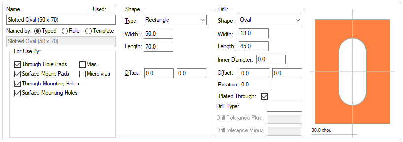
Most drill holes will be of shape Round, but you can define holes which are not round, for example, a slot. To do this select one of the predefined shapes from the drop down list and enter the additional parameters, similar to defining the pad shape. Non round holes can be output as milling data or as X,Y coordinates using a report created in the Report Maker if the slot is to be punched.
Rotation
Long pad styles in Pulsonix are defined pointing up so the length lies along the Y axis. Some long pad styles in customers designs are invisibly rotated by 90 degrees, so the length lies along the X axis. This normally happens when imported from another system, or by using the User-defined pad shape editor to define a rectangle or oval pad with that orientation. Such pad styles will now show ‘Rotated’ next to the pad width and length. Also, if the style is changed to a point shape (like round, square or octagon) the rotation is removed. This way it is possible to change a rotated rectangle to a square and back to a rectangle to remove its hidden rotation.
Drill Type
The Drill Type is a string which designates the drill as a special type. For example Type VII for filled & capped vias. When a Drill Type is defined, you can also define a Plus and Minus Drill Tolerance. Drills of a type can be processed separately in CAM Plots. These values can also be used in the Report Maker
When naming the Drill Type, if using the ODB++ output, it is important to match the naming convention expected in the ODB++ file.
The format should be: Type space followed by I-VII with upper or lower case acceptable. It is converted to upper case in the export. Type IV-a is acceptable, the a is ignored.
Preview
As you create the pad style, the preview is changed dynamically to give you a view on what your pad will look like when used.
Slotted Pads
The Pads Styles page can also be used to create slotted pads.

When a slot is required, use a non round shape, such as Oval, Rectangle or Rounded Rectangle. As well as the Width and Length, you may also be required to provide the Corner Radius for the inside corners. These are then extracted for manufacturing using the Report Maker or drilling output in CAM Plots option.
Adding Pad Shapes By Layer
Layer Exceptions
You may want to define a different shape for a pad style on specific design layers. This can be done by selecting any cell in the Pad Style definition, then clicking the By Layer button on the dialog. You can define the shape for a specific layers. You can also define a shape for all layers of a layer class, for example all power plane layers. You can also define a shape for all Inner Electrical layers.
When multiple definitions may apply, the precedence order is: By Layer; By Layer Class; top or bottom layer side; Inner Electrical; the default pad style shape.
When you have clicked OK from this dialog, a new line is added to the Pad Styles table below the relevant Pad Style row. This new line will have the name of the layer the shape is defined for, along with the shape parameters.

The Layer cell of the Pad Style will also now have a small button. Clicking on this button will expand and collapse any By Layer definitions you have defined for the Pad Style.
You can delete a By Layer definition by selecting any cell in the line and clicking the Delete button on the dialog.
There is a system wide option to mirror padstacks on mirrored components. This would mean that By Layer exceptions would mirror to the equivalent layer on the other side, if such a layer exists.
Micro-Vias
You can also use the By Layer mechanism for setting up pad styles to be used for Micro-vias. You can set up Micro-via Entry Pad and Micro-via Stop Pad exceptions to define the via entry pad size and stop pad size.
Spacing Shapes
You can also use the By Layer mechanism for setting up a Spacing Shape. By defining a Spacing Shape, you can provide additional spacing around the pad which is then used for spacing purposes instead of the actual pad shape.
Pad Stacks in the Design
When defining a pad style, the assumption is that the default pad defined will be used throughout the pad ‘stack’. That is, every layer in the design will use that same pad style unless redefined on a per layer basis using the By Layer feature. That means, a pad style created and used on a footprint that has 4 electrical layers, can still be added to a design that has 12 electrical layers for example and vice-versa (a 12 layer footprint can be used in a 2 layer design).
Units
The Units button allows you to locally switch between Metric and Imperial units whilst in this dialog. Once the dialog is closed, the units revert back to the original design units. If switching to different units to the design units, the value typed will be converted when you next enter this page.
Related Topics
Technology Overview | Micro-vias | Layers | Drill Size Table | User Defined Pad Shape | Pad Defaults | Pad Style Naming | Dialog Grids