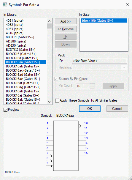
Use this dialog to change the symbols used on a gate.
Shortcuts
Default Keys: None
Default Menu: Edit
Command: Change Symbol
Locating this option
Available from: Library Manager option > Edit button > Parts tab > Edit menu > Change Symbol option
How to Use This Dialog

The dialog displays two lists. The left-hand list shows suitable Schematic Symbols from the Library. The right-hand list shows the symbol (or symbols) currently assigned to the selected gate. To add a symbol from the library to the gate, select it in the left-hand list and press Add. To remove it from the gate, select it in the right-hand list and press Remove.
The pin count filter is defaulted to show only symbols which have the correct number of pins, to ensure that all symbols on the gate have the same number of pins. If you remove all symbols from the gate, you can turn off the pin count filter or change the number of pins.
Use the checkbox Apply These Symbols To All Similar Gates to change all “matching” gates to use these symbols. This is a quick way of making the same change to all gates in a part. If you have any gates with different symbols, for example a power gate, these will be left unchanged.
Where more than one symbol is assigned to the gate, the first symbol in the list will be the one used by default when adding the gate to a schematic design. The second and subsequent symbols can be selected using the Next Symbol command or the Properties dialog.
Use Preview to switch on/off a preview of the currently selected symbol.
Vault
If the Vault is in use, the Vault section,
displayed below the right-hand list of symbols,
will show the Vault ID and Revision for the currently selected symbol.
By default, Revision shows the
A symbol that is not from the vault, will be shown as such in the ID field.
