This page of the Parts Editor allows you to define the schematic gates or part representations contained in this part group, together with the logic names and gate and pin swapping information.
Locating this option
Available from: Library Manager option > Edit button > Parts tab > Gates page
How to Use This Page
There is one line in this grid for each pin that belongs to a gate in the part. All the pins for each gate are grouped together, as shown below.
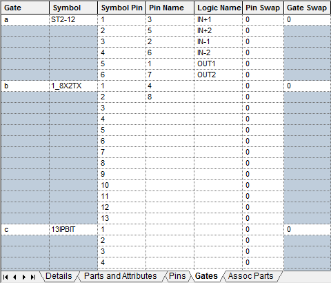
To insert a gate into the part, use the Insert Gate command.
The default symbol to be used for the gate is shown in the “Symbol” column. A different symbol can be selected by choosing from the drop-down list. To change the list of symbols assigned to the gate, select the Change Symbol entry from the bottom of this drop-down list.
The Pin Name for each pin can be selected from the drop-down list that contains all the pin names defined on the Pins page. The Pin Names mapped to gate pins may be checked by using the Check Pin Mappings option.
The Logic Name should be descriptive of the function of the pin. It does not have to be unique. It is possible to define the default logic names in the symbol, these will be the values initially used, but you can change them to suit. The logic names defined in the part are the ones actually used in a design. If the Symbol already has a Logic Name attribute assigned to it, using Apply Symbol Logic Names option in the Part Editor will take the logic name from the symbol and put it onto the Logic Name field of the Part. This option is available on the context menu when you right click over any of the Gates grid.
Part Representations
A Part Representation is a set of gates which can be added to a schematic. A Part can have more than one representation. For example, a pack of four gates could be represented by a single top level symbol, or as four individual gates. Each representation is independent of the others. There is no cross checking, so representations do not have to conform to a hierarchical structure, although this is likely to be the case. The first representation is the default, used when a component is first added to a schematic.
On selection of the first Representation in the Symbol column, the symbol preview will display the symbol or symbols used (2):
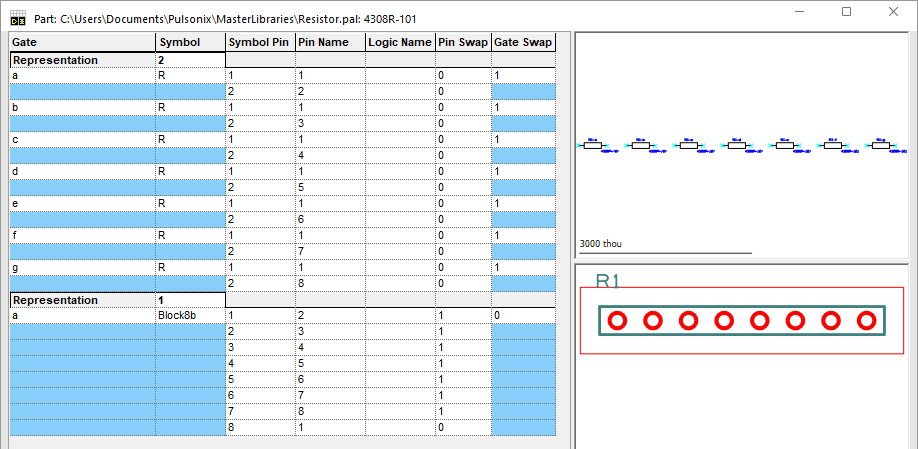
To add representations to a part use the Insert Part Representation command. By default, the representations take numeric names, but you can edit the name shown in the grid to something more meaningful. Each representation must be uniquely named within the part.
Once you have added a new representation, you will need to add the appropriate gates and pin mappings.
On selection of the second Representation in the Symbol column, the symbol preview will display the symbol used (Block8b):
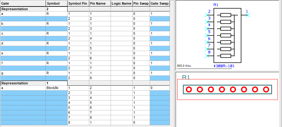
The Change Representation Order command allows you to change the order of the part representations.
When you use the part in a schematic, you can change the component to use one of the other representations defined in the part. This can be done on the Insert Component dialog, using Properties, or using the Next Part Representation command.
Swap Group
The values specified for Pin Swap and Gate Swap are used by the Automatic Gate & Pin Swap, Swap Gate and Swap Pins functions.
Pins within the same gate with the same Swap Group are considered to be swappable, as are gates with the same Swap Group. A pin or gate with Swap Group set to zero is not swappable.
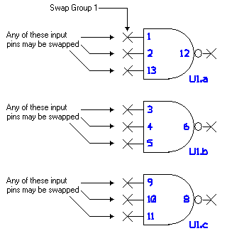
In the example shown here, the input pins have been set to pin swap group 1 to allow swapping between them in each gate. Also, the gates have been set to gate swap group 1 to allow each gate to be swapped both internally within a component and externally between different components using this part.
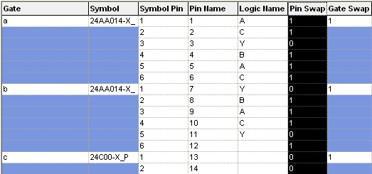
This diagram gives you an idea of how these swap groups would apply to the actual pins on the symbols.
Note: when setting up pin swap group numbers it is worth considering a Back Annotation option in the General Options dialog. This allows you to indicate how a pin swap is performed in the schematic design based on the sign of the swap group. For example, you can say the all pin swaps that have a negative swap group number swap the connections in the schematic, rather than swapping the pin names.
Using Copy and Paste To Edit Values
The values in this grid can be manipulated using the normal Copy and Paste techniques associated with spreadsheet applications such as Microsoft Excel. This includes the ability to copy and paste multiple rows and/or columns of data. One possible use would be to copy the pin data into an external spreadsheet to take advantage of advanced features such as sorting and filtering, then paste the modified data back in to the Part Editor. When pasting from an external source it is important to ensure that the data is arranged in the same order as the cells in the grid.
The Copy and Paste commands are available from the Edit menu on the top menubar or via the right click context menu. Alternatively, the defined shortcut keys, by default Ctrl+C and Ctrl+V, may be used.
Selecting cells to copy or paste
A single grid cell or a range of grid rows and/or columns may be selected for
copy or pasting. By default, clicking on a cell causes that cell to enter
edit mode indicated by a flashing cursor and any copy or paste will
be directed to the edit control or dropdown list for that cell (although the
Edit on Double-Click only
option does allow the grid to be switched to a more traditional spreadsheet
mode of operation). If, rather than clicking, the mouse is dragged while the left
button is held down a range of cells may be selected, indicated by being shown
in reverse highlight. This range of cells can now be copied or pasted as a whole.
If a single cell has already been selected by clicking, it is possible to extend this into a
range of cells. First, if the cell is in edit mode, press the
Pasting Values into the Grid
When data is pasted into grid the values are subject to the normal constraints of the column into which they are being inserted. Any invalid values will not be inserted. For example, a value pasted into the Pin Name column must be a valid Pin Name defined in the Pin Names column of the Pins page.
The Gate and Symbol Pin columns are read only and as such may not have values pasted into them although they may be selected and copied.
The cells affected when pasting is dictated by the range of the cells copied not by the range of cells currently selected in the grid. So copying a 2 by 3 range of cells and pasting into the grid will paste a 2 by 3 range of cells starting at the top left cell of the currently selected range, subject to the constraints of the columns affected.
One exception to this is when pasting a single value into multiple cells. All cells in the current range of cells will be set to the pasted value, again subject to the column constraints.
Mapping Multiple PCB Pads to same Schematic Pin
Pulsonix allows you to model certain types of component that have ‘internal’ connections within them. It also allows those that have multiple internal pins that need to be assigned to the same net, for example, the ‘casing’ of some transistors. This is an alternative method to connecting pads together in the footprint by adding to the same net or using wires.
This is detailed on a separate page, please refer to the Mapping Multiple PCB Pins to same Schematic Pin page.
Net Names
Importing Pin Data from other sources
It is also possible to import values for the pins from external files using the Import Pin Data option.
Related Topics
Parts Editor | Insert Gate | Change Gate Symbol | Automatic Gate and Pin Swap | Swap Gate | Swap Pins | Insert Part Representation Mapping Multiple PCB Pins