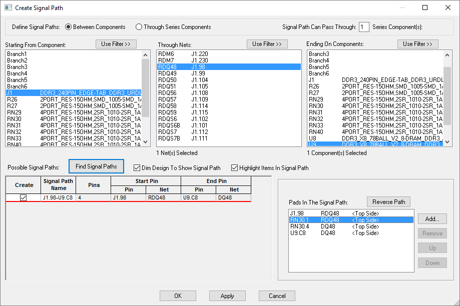
This dialog leads you through the process of creating a signal path. A Signal Path is an ordered set of pins which can span several nets. So the path may pass through one or more Series Components. You can then apply length and other rules to this set of pins and the connections between them. A Signal Path can also contain Branch Points, these can act as a terminating point for one or more Signal Paths.
The dialog allows you to define several signal paths at the same time. This may be useful if you are trying to balance path lengths from a source to several target pins.
Instructions on controlling the in and out pins on a series component can be found here.
Shortcuts
Menu: Setup
Default Keys: T
Command: Technology
Locating this option
Available from: Setup menu > Technology option > Signal Path tab > New button > Create Signal Paths dialog
Available from: Design > Interactive pad selection Context menu > Create Signal Path option
Create Signal Path

Using this dialog
Choose how you want to define the Signal Path:
Between Components use this if you know which component and net for the source pin. You can specify the Starting From Component and Ending On Components, then press Find Signal Paths to find the possible signal paths between these components, passing through upto the specified number of Series Components.
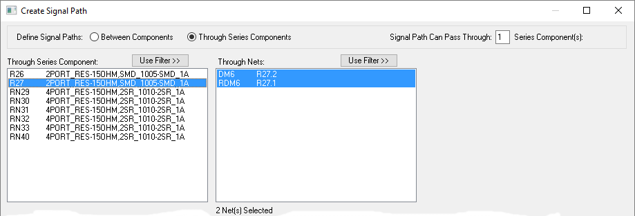
Through Series components use this if it would be easier to choose the component in the middle of the path. Series Components are usually 2 pin components. Press Find Signal Paths to find the possible signal paths passing through this component. With this mode selected, the dialog changes to show you just the Series components in the design.
Use Filter
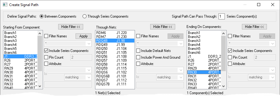
Each of the lists in the upper half of the dialog has a filter which can be used by pressing the appropriate Use Filter button.

Dim Design To Show Signal Path
Select this check box to dim the design to show the signal path being selected. This is useful to confirm you are selecting the correct path, you can also interactively select the components instead of selecting in the lists.
Highlight Items In Signal Path
Used in conjunction with the Dim Design check box, this further highlights the signal path selected.
Signal Path Can Pass Through
You can define how many Series Components the signal paths will pass through (typically 1). A series component is a two pin component, or a two pin gate on a larger component. Both pins must be connected to different Signal nets (i.e. not Power or ground nets).
Note that the two pin gate can be defined on any representation of the part, not necessarily the default or current one.

Define Signal Paths Between Components
The upper part of the dialog is divided into three lists.
Starting From Component
This list shows the possible starting (or source) components. Press Use Filter to filter the list using the filter controls which appear.
Select the required starting component. A list of pins on that component and their associated nets appears in the Through Nets list.
It is also possible to interactively select the required component in the design.
Through Nets
Select one of more pins as your source pins. Again, this list can be filtered by pressing the Use Filter button.
Ending On Components
Select one or more end components. You can select more than one end component because you can define more than one Signal Path at once. This list also has a filter accessed by pressing the Use Filter button.
It is also possible to interactively select the required component in the design.
Find Signal Paths
Once you have made you selections above, press Find Signal Paths to list the possible Signal Paths. See below.
Define Signal Paths Through Series Components
The upper part of the dialog is divided into two lists.
Through Series Component
This list shows the possible series components. Press Use Filter to filter the list using the filter controls which appear.
Select the required series component. A list of pins on that component and their associated nets appears in the Through Nets list.
It is also possible to interactively select the required component in the design.
Through Nets
For a two pin component, this list is for information only. If you selected a multiple gate component there could be more than one possible pin pair, in this case you can select one or more pins.
Find Signal Paths
Once you have made you selections above, press Find Signal Paths to list the possible Signal Paths. See below.
Find Signal Paths
When the button Find Signal Paths is pressed, a list of possible Signal Paths will appear in the lower grid. To create a Signal Path, check the Create box for the appropriate row. The name of the Signal Path is defaulted to the names of the start and end pins, but you can change it, as required.


Pads In The Signal Path
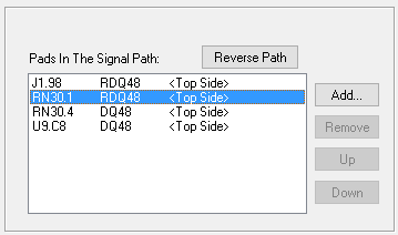
This box shows all the component names, pins, net names and side for the selected signal path. You can add extra pins to the path by using the Add box. The Choose Pads dialog is displayed from which to choose valid pads. Once selected these will be added to the Pads In The Signal Path list. Now that additional pads have been added, you can select them, and the Remove button will be available. Use the Up and Down buttons to change their order within the same net. The order defines the connection pattern within each net.
Create the Signal Paths
Once you have selected some signal paths to create. Press OK to take you back to the Technology dialog, Signal Paths page.