Insert Track is the manual operation to translate net connections in the design into copper tracks. It allows you to interactively lay down tracks to physically run copper between all the component pins on each net.
Choose between using a ‘single shot’ method to add single tracks, or entering Insert Track Mode to sequentially add multiple tracks.
Shortcuts
Default Keys: None
Default Menu: Insert
Command: Insert Track
Mouse: Double-Click
Locating this option
Available from: Insert menu > Track option
’Single Shot’ Insert Track
Whilst in Select Mode or Edit Mode do the following:
- Double click the mouse on a connection.
- Select a connection and right click to use the Edit Segment option from the shortcut menu.
- Double click the mouse over a component pad.
This is a ‘One Shot’ add of a single track. Once the track is completed, you are automatically put back in to Select Mode.
How To Use Insert Track Mode
- From the Insert menu, select Insert Track , or use one of the above mentioned shortcuts. This takes you into Insert Track Mode.
- If another track is pre-selected, then the width and layer are taken from the selected segment to use when adding the tracks in this session. This is the same as changing style prior to adding the new tracks now. Also, if a new net is created for the new track, it will use the net class from the pre-selected track. The pre-selected track will remain selected until the first track is added.
- Before you select an item to start the track from, you can right click the
mouse to use the shortcut menu to do the following:
-
Change Layer - Use this to set the layer that you wish the track to be on. This layer is used if the picked item to start from reaches it, otherwise the layer the start item is on will be used. If Draw Current Layer On Top in the Display Options is set, the picture will be redrawn to show all items on this layer on top.
-
Change Style - Use to change the width of the track to a specified value. This value will be used even if the picked item is already on a net. The new style is shown on the status bar.
-
Use Default Track Style - Use to change the width of the track back to using the default style. The style on the status bar is cleared to indicate that the track style will be defaulted as follows:
If the track has default track styles defined through the Net Styles dialog the default track style is the nominal width on this net style entry, otherwise the default track style is taken from the default design settings.
-
Start Track Hugging - Use this to pick another track or shape to follow closely by locking on to it.
-
Follow Construction Lines - Use this to start a new track on the closest construction line. The track will follow along the construction line and automatically corner when you reach an intersection with another construction line.
-
Change Grid - Use to change the grid that the track segments will be placed on.
-
- Select an item to start the track on as follows:
- Click on any item on a net in the design. e.g. pad, via, copper, track, template, etc.
- Click the mouse on a PCB connection. A track will be added to the item at the nearest end of the connection.
- Click the mouse on the dangling end of an exiting track, differential pair or bus route. You will end up adding segments to the end of the picked item. If you do not want to add segments to a differential pair or bus route, press the Ctrl key down when clicking the mouse at the track end and a new single track will be added to the end of the picked track.
- Click the mouse in space. A new track will be started from the position you picked. The track will not be connected to anything at it’s start. If you want to start a new track within the picking distance of an existing item, keep the shift key down whilst clicking at the start position. The track will not attach to any existing items.
You now have a new track dynamically displayed on the screen and are ready to add the track segments.
New Track Details
Information about the new track will be shown on the Status bar.
Start Item
The track will be started from the picked item. If a connection is picked then the track will be started from the item at the end of the connection that is closest to the picked position.
Net
The picked start item defines which net the track is on. If the start item is not on a net, or there is no start item, a new net will be created using an internally allocated net name of the form $1, $2, $3… etc.
Width (Track Style)
Shows a track style if Change Style was used to replace the default style.(see above).
Note: If an existing track segment was picked to start the track from, and the Edit Track Option Use Style From Picked Track is enabled or the existing track segment is selected, the new track will take its width from the picked track segment.
Layer
The track will be on the default track layer unless Change Layer was used (see above). If the picked item to start from does not reach this layer, the layer the start item is on will be used.
Special Note On Routing A Connection
The advantage of routing a connection is it stays on the end of the track whilst the track is added. This indicates where the track is to be routed to. It also indicates if the track is part of a differential pair or signal path, which might have a bearing on the default track style to be used.
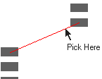
 | So that the system understands that you wish to route a PCB connection, select the connection slightly away from the pad. This indicates that you wish to route a connection and that you wish to start the connection from the pad close to where you picked. |
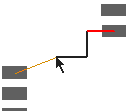
 | The manual routing operation will start: As you insert the track the connection will remain at the end of the track until the connection is completely replaced by a track: |
Adding The Track Segments
Once the track is started, the track segments can be added by clicking to add corners. You can right click to use the shortcut menu to access various editing options, some of which are listed here:-
Change Grid to ensure tracks are placed on predefined grid points.
Change Layer by inserting vias through the board.
Change Width of individual segments to neck down between close obstacles.
Change Net to alter the name of the new net you are adding.
End On Via to add stub tracks from a pad to a power plane using a via. Note, there is an Option to protect all vias added using this feature against automatic delete.
End On Testpoint to add place a testpoint on a net.
Show Connection To Net to indicate which is the closest item on the net to the current track end position.
Complete As Track to automatically complete the track from the current position to the end of the attached connection.
Use Finish Markers to indicate when you are over an item that the track can finish on.
Online DRC and Display Clearances to help avoid getting too close to obstacles on other nets.
Push Mode gives a sub menu of Track Pushing options.
Change Segment Mode to define if angled, curved or orthogonal segments are added.
Orthogonal Mitre to automatically add mitres or curves between orthogonal segments.
Auto Corner to make it easier to add tracks without having to click to add corners.
This procedure, and the options you can use, is described in detail in the Edit Track documentation.
How To Finish A Track
The following Edit Track options affect the completion of a track:
- Finish Markers
-
If enabled, the cursor will change to an ‘F’ to indicate that single clicking will finish on the item under the cursor rather than add a corner.
-
- Allow Join Nets - If not enabled, you will only be able to select items to finish on that are on the same net as the track you are adding. If enabled you will be able to [Join Nets](#joining nets).
- End Track On - Use to end the track on a Via or Testpoint.
- Double Click Completes Track
- Use to set double click in space to automatically complete the track from the current position to the end of the attached connection
Use one of the following methods to finish the track:
-
Click on any item on a net in the design. e.g. pad, via, copper, track, template, etc. Keep the Ctrl key down if the item is on a different layer, a via will be introduced.
-
Double click the mouse in space. The track will end at the position you picked. The track will not be connected to anything at it’s end unless the End Track On feature is being used.
If the Double Click Completes Track option is enabled and a connection is attached to the track end, the track is automatically completed using the current segment mode to the item at the end of the connection. If Online DRC is being used, and there are obstacles in the path to the target item a more advanced algorithm will be used to route to it.
Joining Nets
If you are connecting to an item on a different net you are presented with the following warning:

The net being added will be merged into the net to which it is connecting.
Adding More Tracks?
You may continue to add further tracks by repeating the [How To Use Insert Track Mode](#insert track mode) instructions above. Once you have finished you may exit Insert Track Mode by pressing Esc on the keyboard, by right clicking the mouse and selecting Cancel Insert Track or by selecting an alternative command from the Toolbar or Menu.
Adding Tracks Using Impedance Rules
If you wish to add tracks and for the system to calculate your track thickness for you based on the required impedance, then you need to define Track Impedance Rules and enable the Use Impedance Width For Track Style routing mode in the Options dialog.
More detailed information can be found on the Edit Track Impedance page.
Below is a summary of process required:
- You must have the High-Speed option enabled on your license; this feature is a cost option.
- Enable the Use Impedance Width For Track Style option in Options and Edit Track page.
- You must set up a realistic Layer stack in the Layers dialog along with the actual Material thickness to be used.
- Define the Track Impedance Rules in your Technology.
- Start manual track routing and the Track Width will be calculated for you.
Related Topics
Allow Join Nets | Auto Corner | Orthogonal Mitre | Display Clearances | Edit Track | End Track On | Grids | Online DRC | Remove Track Loops | Segment mode | Show Connection To Net | Show Finish Markers | Track Pushing | Status bar | Technology | Track Properties