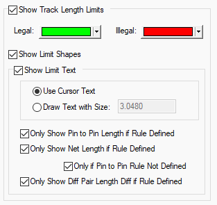
Use this to set up preferences that affect how track length limits are displayed dynamically when adding or editing tracks in a PCB design. These give you a head up visual indication of how long the connection is and how well it complies with any limits imposed by length rules. The limit indicator will dynamically follow the cursor, and continually update.
Using the Track Length Limits Tab
All of these options are saved to the registry, so they apply to all the PCB designs you load into the application.

Show Track Length Limits
Check this option to show length limit shapes or text in general. Whilst using Edit Track, the length limits can also be turned on or off using the shortcut menu Editing Options - Show Track Length Limits.
The text and shapes are colour coded to show Legal and Illegal values. Green and Red are the defaults, but you can use any colours.
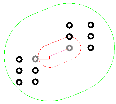
When you are within the maximum track length limits, the limit shape or text is drawn in the legal colour. When the maximum limit is exceeded, the shape or text is drawn in the illegal colour and the shape will grow as the excess increases. Minimum limits are always drawn in the illegal colour in a dashed style, until the minimum is exceeded, when the shape is not drawn.
Show Limit Shapes
Limit Shapes give you a visual indication of how far the track can extend and still be legal. You should be able to legally reach any point between the inner and outer shapes.

Show Limit Text
The limit text gives information about the current estimated length and length limits that apply.
Use Cursor Text, uses the system defined tooltip font and text size The text has a background box drawn in the current background colour.
Draw Text with Size, inbuilt font drawn at the given text size. The size is given in the current design units, but you can specify other units on input (e.g. 3mm). The text has no background so improves visibility of surrounding items at the expense of readability.
You can alter the distance the text box is from the cursor using the Interaction Option - Cursor Text Offset From Cursor. You can also use the Reposition Cursor Text command (available from the context menu
- Editing Options), which shifts the cursor text into the next quadrant.
Pin to Pin Length
The Pin to Pin Length is the track length between the two nearest Component Pins or Branch Point by tracking a path from each end of the connection being edited. This length will follow through vias. The names of the two pins will be show along with the length.
You can choose to Only Show Pin to Pin Length if a rule is Defined which limits the length of the Pin to Pin connection.
Net Length
The Net Length is the total track length within the current net.
You can choose to Only Show Net Length if a rule is Defined which limits the length of the Net. More specifically, you can choose to Only Show Net Length If a Pin to Pin Rule is defined which limits the length of the connection.
Differential Pair Length
The length of a Differential Pair is the track length of the path between the start and end pins of the selected side of the pair.
You can choose to Only Show Differential Pair Length if a rule is Defined which limits the length of the Differential Pair.
Length Rules
You can define Track Length Rules (explicit length limits) and Track Length Match Rules (length Limits defined by comparing with other lengths) in the technology.
You can also define track length limits on a Pin Network Part.
You can also show pin to pin length limits without rules being defined in the technology by using the Match Pin To Pin Length option when editing tracks.
How Limits are Calculated
The connection you are editing may be part of a number of length limited items - Nets, Differential Pairs, Signal Paths or Sub Nets. The lengths and applied rules are evaluated for all of these, and the most limiting rules are found. The rule which most limits the minimum length may not be the same rule which most limits the maximum length. The two most limiting rules are the ones which are displayed. It could be possible that the minimum and maximum are such that it is impossible to satisfy both without making wider changes to the design.
How the Lengths are Calculated
The lengths are calculated by adding the lengths of all the tracks which make up the Total or Pin to Pin
Length of the length limited item (as required for the rule being evaluated). Unrouted sections, or
trailing segments are estimated using a 45 degree plus orthogonal projection. Length adjustments are
also applied using Track Length
Factor Rules, Layer Change Length
Rules and
Other Options Tabs
| General Options: | Design Backups | Display | Edit Shape | File Extensions | Find | Folders | General | In-Place Names | Macros | Move | Multi-Screen | Pan & Zoom | Resolve Net Names | Select | Synchronisation | Tooltips | Warnings |
| PCB Options: | Edit Track | Interaction | Online DRC |
| Schematics Options: | Edit Connection | Interaction | Online ERC |
| Footprint Options: | Edit Breakout |
Related Topics
Edit Track | General Options | Nets | Differential Pairs | Signal Paths | Sub Nets | Match Pin To Pin Length | Technology - Track Length Rules | Technology - Track Length Match Rules | Technology - Pin Networks | Rules Spreadsheet Bar